0
\$\begingroup\$

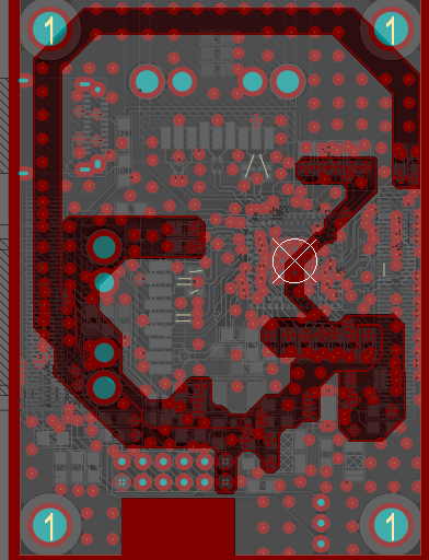
I'm working on a Raspberry Compute Module 4 Carrier with an USB 3.0 Controller with High Speed signals. As I read here in other thread, I decided change polygons for power planes, but I have 2 doubts about them:

-What can I do with the white space? I have 4 split planes, Should I connect all the excess plane to GND or one of the power supplies?

-Other doubt, Can I route high speed signals over power split planes? I have read about not routing over ground split planes, but I'm not sure if I can do with power planes.

About differential pair impedance, the height of the trace is from their respective planes or from GND plane? I'm not sure from where I should to measure the height (my stack up have 4 layers).

Thank you so much!

enter image description here

Edit: Thank you so much for your answers. I have reorganized the PCB and avoid that the traces cross split planes. On Texas Instruments Forums I have received an answer that recommends to me doesn't route on power planes references, he advice to me change my design to 6 layers. Other mate here have told to me that route my signals in inner layers but Texas Instruments doesn't recommend route high speed signals on inner layers. Is the best option add more layers?

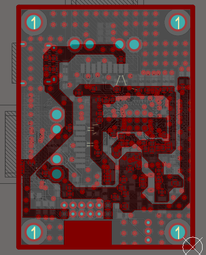
New power plane

\$\endgroup\$
4
  • 1
    \$\begingroup\$ don't run high speed traces whether it is single ended or Differential over split plane. No excuses in this. Power or GND as reference plane for high speed traces- Prefer GND as reference plane and if you choose Power as reference plane make sure your PDN is good. Which ever is the reference plane to carry immediate return current finally this current has to reach the source. \$\endgroup\$
    – user19579
    Commented Apr 29, 2021 at 14:48
  • \$\begingroup\$ I fix my split planes distribution so as to my high speed lines don't cross the split planes, but on Texas Instruments Forums they doesn't recommend routing over Power Reference Plane (my stack up is Top-GND-Power-Bottom and I have high speed signals on bottom layer). Should I change my stack up layer to Top-GND-PWR-PWR-GND-Bottom? \$\endgroup\$
    – Juanma
    Commented Apr 30, 2021 at 7:19
  • \$\begingroup\$ If you can afford yes, going to 6 layers will help. Which high speed signals you are talking about like which interface? speed of operation? where is load? can you able to route all high speed over same layer (Top) \$\endgroup\$
    – user19579
    Commented May 1, 2021 at 9:54
  • \$\begingroup\$ They are USB 3.0 lines, and it is imposible to route all on the same layer I think, It will be easier add more layers and use Top-GND-PWR-PWR-GND-Bottom. \$\endgroup\$
    – Juanma
    Commented May 3, 2021 at 6:10

2 Answers 2

1
\$\begingroup\$

On only 4 layers, you have only two options for tightly spaced layers: 1+2 and 3+4. Most likely you need both options to route the high speed stuff. But you also need tightly spaced power and GND areas for the high speed chips.

This creates the situation that you need 3 things tightly spaced: power+GND, sig1+plane and sig2+plane. But you have only two options to realize this.

Therefore some layers need to share functions. And this can only be power and signals because you never percolate ground planes.

But if signal and power are on the same layer, the return plane for the signals will be always ground.

When you cross your signals from layer pair 1 to 2, also provide GND vias for the return to cross from layer pair 1 to 2.

\$\endgroup\$
6
  • \$\begingroup\$ I'm not sure if I understand that you say. You propose I change my stack up layer, right? But I should to have one GND layer according to Texas Instruments recommendations. I couldn't route high speed signals on inner layers, right? \$\endgroup\$
    – Juanma
    Commented Apr 29, 2021 at 6:37
  • 1
    \$\begingroup\$ I dont know your current stackup, so I cant say if my suggestion would alter it. What I am saying is, in 4 layers, if you route properly, your reference plane is almost certainly going to be GND and not power. Therefore, the question of routing over power plane splits might become an irrelevant one. E.g. you can have GND planes in layer 2 and 4 and use both layer 1 and 3 for both routing and power. Changing layers with highspeed is ok, if you keep lengths matches and dont do it too often and you must provide ground vias nearby. \$\endgroup\$
    – tobalt
    Commented Apr 29, 2021 at 7:54
  • \$\begingroup\$ But, I understand your stack up layer like: Top (Signals and power)-GND- Signals and power- GND? 3rd layer would be inner layer and i couldn't routing on it, wouldn't be? Maybe I understand wrong idea and you suggest use inner layers as GND and combine power and signals on top and bottom. \$\endgroup\$
    – Juanma
    Commented Apr 30, 2021 at 7:23
  • 1
    \$\begingroup\$ You understand the stackup as I meant it. You could also reverse 3 and 4 and have GND on 3 and power+signal on 4. It won't change much. You can route also in 3 (when 4 is GND). The impedance will be essentially the same as on layer 1+2 because the distance from 3 to 4 is much smaller than from 3 to 2, so the GND plane in layer 2 will almost not matter for signals on layer 3. Essentially the two plane pairs 1+2 and 3+4 form independent PCB, putting it slightly exaggerated. Sorry if I wrote in an ambiguous way. \$\endgroup\$
    – tobalt
    Commented Apr 30, 2021 at 7:55
  • \$\begingroup\$ Thank you so much for your answers, I hesitated if I understood you because I thought it wasn't bad idea routing high speed signals on inner layers. Add 2 more GND layers would be easier, wouldn't it? \$\endgroup\$
    – Juanma
    Commented Apr 30, 2021 at 8:08
1
\$\begingroup\$

First of all, high speed signals don't care if the plane is power or return (GND). A trace carrying a high speed signal will couple to either or both of them, depending on the distance (height) from the trace to the plane(s).

That being the case, you want to avoid running high speed traces, across splits in planes. If you absolutely have to do that, then you want to place capacitors across the gaps in the planes, near where the trace crosses the gap.

Differential signals are somewhat more forgiving, but you still want to follow the same rules for routing high speed single ended signals.

\$\endgroup\$

Your Answer

By clicking “Post Your Answer”, you agree to our terms of service and acknowledge you have read our privacy policy.

Not the answer you're looking for? Browse other questions tagged or ask your own question.