2
\$\begingroup\$

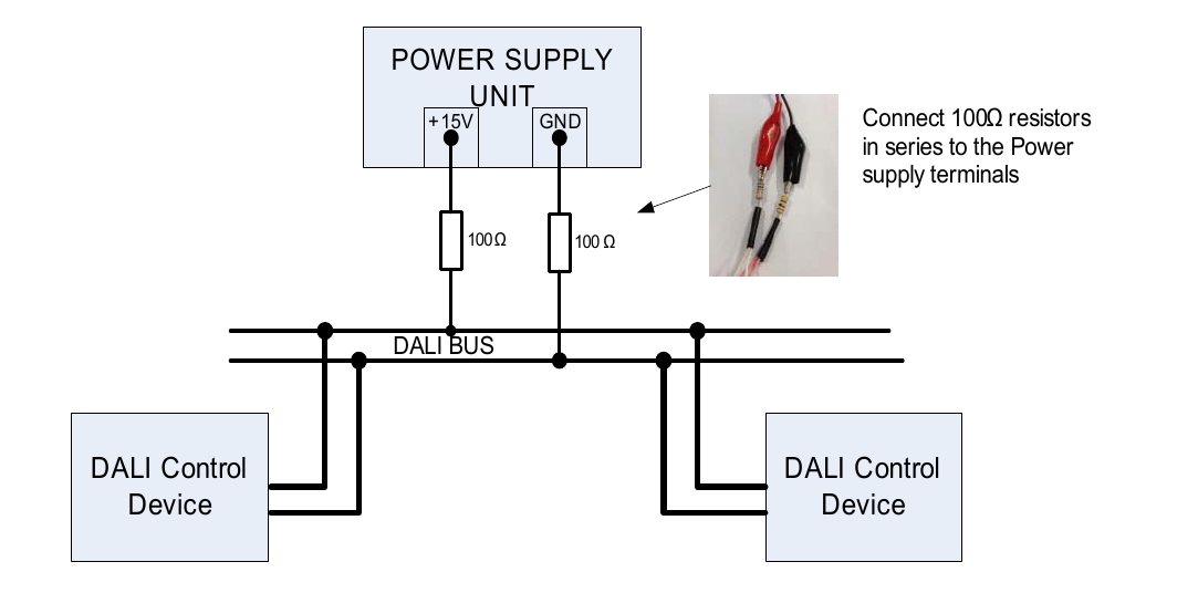
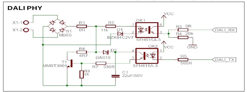
I am starting with the DALI protocol and already was able to send/receive commands based on this project. With comments from a related question I improved my circuit and the quality of my signal. The current circuit follows following schematic and wiring guide and the library for Arduino NANO

enter image description here enter image description here

In the power line two 100_Ohm resistors are needed in series. This however will drop my bus voltage from 15V to 7.8V and the DALI-line shows the broadcasted signal on the osci, but the command is not recognized. This is probably because the bus line should be between 12-24V.

Increasing the supply voltage to 40V also increases the line voltage >12V. Here the commands are recognized, but the circuit draws almost 350mA and the standard metal resistors are over their limit. I was also able to detect all channels (1.driver-> 3 Channels, 2.driver->1 Channel)

What is the reason of the 100\$\Omega\$ resistors?

They act as voltage dividers, where I would understand that I need a current limiter to supply the bus with max 250mA. I also tried removing the resistors and the current limit of the power-supply was triggered (1A) where the voltage dropped to 2.5V. (Only for <1s, the circuit is not damaged).

\$\endgroup\$

1 Answer 1

1
\$\begingroup\$

Using two 100 ohm resistors does not make a normal PSU into a DALI PSU. Either buy a DALI PSU using the list of certified products, or add an LM317 circuit to your PSU as mentioned in the linked question. If you ever use a PSU with a current limit higher than 250mA with DALI equipment, as soon as a device tries to transmit it may damage the transmit transistor.

If your 15V supply is dropping to 7.8V after 200 ohms, it implies that your circuit is drawing 35mA. Unless specifically denoted as bus powered, DALI interface circuits must not draw more than 2mA per device under all conditions whilst not transmitting. So Infineon get away with 2x100R as current limiters for their special case of 2 devices on a bus but it is a terrible idea and totally non-compliant.

Application notes will have disclaimers about using them without doing your own calculations but manufacturers need to do better since they know that many beginners will assume that they are sufficient. Another common mistake on DALI app notes is to omit any rise time control components.

\$\endgroup\$
1
  • \$\begingroup\$ This seems to be the logical answer, now that I read it. I will add the classic LM317-current-regulator-circuit,redraw my circuit, test it and hopefully eliminate my voltage problem \$\endgroup\$
    – v3xX
    Commented Apr 29, 2021 at 7:44

Your Answer

By clicking “Post Your Answer”, you agree to our terms of service and acknowledge you have read our privacy policy.

Not the answer you're looking for? Browse other questions tagged or ask your own question.