1
\$\begingroup\$

I am currently using ZXCT1009 high side monitor for monitoring the current consumption on a bus line for an embedded system we are developing. I am currently using tek scope with Labview for automation purpose. Works good at our lab.

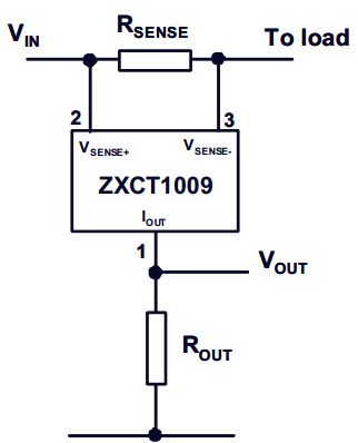
Now I am thinking of implementing this ZXCT1009 in the embedded design itself and somehow sensing the voltage across the output resistor.

ZXCT1009 data sheet -http://www.diodes.com/datasheets/ZXCT1009.pdf

I am not sure how to move forward along the lines of using ZXCT1009 as a battery current monitor.

\$\endgroup\$

1 Answer 1

3
\$\begingroup\$

The datasheet itself provides the schematic for implementing the ZXCT1009 as a current monitor:

High Side Current Monitor

  • Select Rsense such that the expected maximum possible current generates just under 1.1 Volts across Rsense (Rsense = 1.1 / Imax) - going by the limits in the first graph on Page 3, not by the 2.5 Volt specified in the table on Page 2.
  • Select a suitable value of Rout, to give a Vout range suitable to one of the available ADC channels of the microcontroller, for a full-scale Iout of around 10 mA (Rout = 5 / 0.01 assuming a full-scale of 5 Volts)

As the current flowing through Rsense changes, so will Vout. Read this into the ADC, process as required.

\$\endgroup\$
1
  • \$\begingroup\$ Wow, that's rough... you have to tolerate a 1.1V drop before your load comes into play... I guess "Load" could be a regulator or step-up converter and you'd increase V_in accordingly to use this part. \$\endgroup\$
    – vicatcu
    Commented Jan 28, 2013 at 16:55

Your Answer

By clicking “Post Your Answer”, you agree to our terms of service and acknowledge you have read our privacy policy.

Not the answer you're looking for? Browse other questions tagged or ask your own question.