0
\$\begingroup\$

I'm thinking way ahead about a possible future project which will contain, among many other things, a "DIY hearing aid" of sorts. Microphones feeding earbuds with some DSP in between, all in a physically small space. Not because I'm hard of hearing, but to account for an acoustic lowpass caused by a different part of the project.

I have some experience using digital live audio systems that claim about 1ms latency from the ADC's, all the way through the (quite involved) DSP, to the DAC's. In other words, a stereo recorder hooked up to a Y-splitter at the ADC input for one recording channel, and the DAC output for the other recording channel, would measure about 1ms offset between them. (see the test circuit below)

That's fine for a concert, where you can easily have more physical offset than that (~1 foot) between the mics and speakers, but for my project, I'm looking at several inches at most.

So, to get a feel for what I'm stuck with, and how much I need to optimize and overpower my DSP code to fit in the time remaining (small buffers, even down to a single sample just to get it out NOW!, which means I can't use SIMD instructions - increased sample rate, not for "audiophool" quality but just to shorten the turn-around time - etc.), what latency can I expect for a typical audio CODEC chip in this test circuit?:
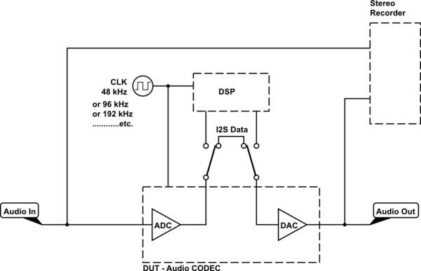
schematic

simulate this circuit – Schematic created using CircuitLab

I expect a minimum of 2 samples, just because of how I2S works - latch and shift out from the ADC, then shift into the DAC and latch again - but I imagine that the conversions themselves aren't instantaneous either.

I've looked at a few datasheets and, at least for the cheap ones, I can't find a parameter that tells me the overall latency. For their intended application of PC audio, I can understand that it's not important, but for this project, it kinda is.

What parameter(s) should I be looking for in a good datasheet? And are there any rules of thumb / tribal knowledge that would be useful as well, in terms of realtime DSP where the output might combine with the original input, after a small speed-of-the-wave delay of the original input? (1's of samples at 48kHz)


Of course, all of this might not even matter, depending on the acoustic lowpass that I end up with, for which this DSP needs to be a complimentary highpass with transducer-correction and peak-limiting. I have no idea what that acoustic lowpass is going to be, so I'm looking for enough general information that I can evaluate it when the time comes.

(If the crossover frequency ends up being low enough and steep enough (overall latency is a small fraction of a single wave), this may all be a moot point; I'm not going to hear the original anyway, where it matters, so just throw some pre-fab code at it and call it good. Or the crossover might be high or gradual enough that it does matter...)

Anyway, I'm looking for enough general information that I can evaluate it when the time comes. Thanks!

\$\endgroup\$
10
  • 1
    \$\begingroup\$ Why not go pure analog to measure phase shift with distance and use a graphic equalizer to wired ear buds. Then latency is only limited by your electronics ( near 0) and 10 to 90% Risetime = 35% of BW 1/f. What is the end result? \$\endgroup\$
    – D.A.S.
    Commented May 7, 2021 at 19:16
  • \$\begingroup\$ An equalized spectrum of what medium? Graphic equalizers can be made pretty tiny. \$\endgroup\$
    – D.A.S.
    Commented May 7, 2021 at 19:22
  • \$\begingroup\$ If you can’t make it work with pure analog, it will be even harder with a DSP. \$\endgroup\$
    – D.A.S.
    Commented May 7, 2021 at 19:35
  • \$\begingroup\$ The digital filter in the DAC/ADC adds substantial latency also. Might be better off with a SAR ADC, or using the bitstream from the sigma delta directly. \$\endgroup\$
    – bobflux
    Commented May 7, 2021 at 21:02
  • \$\begingroup\$ @TonyStewartEE75 Yes, it would be possible in pure-analog, and that was my original idea, but I won't be able to access it physically while it's running, so some kind of remote adjustment is also required. (get it close in theory, then final-tweak it "live") That's plumb easy to add to a digital design, but represents a pretty big increase in complexity and greatly limited options in analog, as not all topologies are easy or even possible to adjust electrically. (DAC-fed-VCA's and digipots only do so much) \$\endgroup\$
    – AaronD
    Commented May 7, 2021 at 21:46

2 Answers 2

1
\$\begingroup\$

Didn't you just specify the answer?

You said spacing of "a couple inches". Sound is roughly 1ms per foot. Let's assume 4 inches which means roughly 400us (I'm being VERY loose to make the math easy).

At 48KHz, samples are roughly every 20us--so you get 20 samples (400us/20us) to stay within your latency budget.

If you run that up to 192KHz, you get 80 samples.

The codecs are probably close to 1 sample of latency on DAC and ADC if you turn off on-board DSP processing. Nobody actually tries to delay things (unless you have on-board processing and ask them to), but you have to have a full sample in order to transmit/receive on the digital bus.

As for vector instructions, even if you only had 1 current time sample to work with, you've got lots of DSP algorithms which work with quite a few past time samples so SIMD vector instructions would still be a win.

I would also caution you about being too stringent in your audio specifications. Most people have ... quite imperfect hearing. I have created audio systems where there was a variable 5-8% pitch shift (for delay compensation reasons in really bad cases). It was painful for me to hear, but the vast majority of people didn't even notice even after I pointed it out.

I recommend that you set your specifications to the human perception average and allow tweaks for those who are outside the norm.

Hope this helps.

\$\endgroup\$
9
  • \$\begingroup\$ Hmm...your anecdote about most people not hearing a problem that is obvious to you, even after you pointed it out, is encouraging...except that I'm one of those who tends to notice that sort of thing. :-/ Looking at failure modes also seems a bit encouraging even then: if my system is inadequate, it'll be a comb filter, and our ears seem to be pretty good at ignoring those since they occur all the time in nature anyway. So maybe it can work to just let it do what it's going to, with a known-good codebase. \$\endgroup\$
    – AaronD
    Commented May 8, 2021 at 16:57
  • \$\begingroup\$ I know that no one intentionally delays these things, but I also know that there's inherently some required just because of how the process works. So I'm asking about that, more than anything else. In the test circuit shown in the question, how long does it take for an impulse, step-change, or other recognizable feature to make it all the way through? Not just the mechanics of serial communication, but coming up with a digital representation in the first place, and then using it at the end. A SAR ADC, for example, isn't instantaneous, but audio is probably delta-sigma... \$\endgroup\$
    – AaronD
    Commented May 8, 2021 at 16:59
  • \$\begingroup\$ You are arguing with the datasheet about "sample rate". The datasheet says a sample drops every 20ms at 48KHz, so that's what happens. These aren't mega-speed RF ADCs that deep pipeline because the analog sample rate and digital data rate are similar. Nobody keeps a pipeline of analog samples around at audio speeds--that would be a waste of silicon. The delta-sigma converters are internally being clocked at many MHz (20MHz+), not KHz, and work one audio sample at a time. Audio is sloooooow relative to the digital blocks. Consequently, the delta-sigma audio clock latency is 1. \$\endgroup\$ Commented May 9, 2021 at 1:29
  • \$\begingroup\$ "Nobody keeps a pipeline of analog samples around at audio speeds--that would be a waste of silicon." Not intentionally, no. I never claimed that anyone did. "...and work one audio sample at a time." I knew they were super-fast, low-resolution converters that were "noised up" on purpose (all high-frequencies) and then lowpassed to both fill in the lesser bits and remove that noise before taking every 1000th sample or whatever and throwing away the rest, but considering that 1) that's some DSP work in the converter itself, and 2) DSP usually implies non-zero latency...... \$\endgroup\$
    – AaronD
    Commented May 9, 2021 at 2:57
  • 1
    \$\begingroup\$ I expect so, yes. However, I would recommend that you go dig at delta-sigma converters. You have some misconceptions about them that you probably want to correct before throwing DSP algorithms on top of their outputs/inputs. Delta-sigma converters do not throw samples away--they oversample it quite a lot and their comparators are very high resolution. Delta-sigma does not add noise inherently, but it does shape the base noise. Finally, adding noise (called dithering) in fact increases the overall noise floor even at low frequencies, but breaks up sampling artifacts. Good luck. \$\endgroup\$ Commented May 10, 2021 at 10:49
0
\$\begingroup\$

What parameter(s) should I be looking for in a good datasheet?

I think I finally stumbled onto the answer for this one. It's called "Group Delay", as on pages 16 and 20 of this datasheet. It appears to be measured in samples, though the datasheet gives the unit in seconds and the number as x/Fs.
Page 21 gives the valid sample rates for each mode.

I had to google "group delay", because it wasn't something I was familiar with, and found this useful explanation. So in the context of an ADC or DAC filter, it seems that the converter itself does indeed delay the signal by that many samples.

In the case of the one linked here, that's 12 or 9 samples for the ADC at 48kHz or 96kHz, respectively, and 10 or 5 samples for DAC, for a total round-trip of 22 or 14 samples from analog in to analog out, just in the converter chip itself.

Converting to time and then distance in air gives ~460us|~6in|~15cm or ~150us|~2in|~5cm.

I think I can work with the shorter of those, provided I can keep up with twice the number of samples! Even if it does comb-filter at the very top end (the wavelength of 20kHz in air is ~5/8in|~1.5cm), it's pretty well attenuated acoustically (the reason this project exists in the first place) so it's probably not noticeable. As long as it lines up closely enough through the crossover region (acoustic lowpass, DSP highpass), I'll be happy.

Interestingly enough, the delay figure for 48kHz is almost half of the 1ms that the commercial live sound gear advertises for its total latency. I guess it would be reasonable for some complex routing and a handful of transports to take the other 26 samples or so.

And are there any rules of thumb / tribal knowledge that would be useful as well, to avoid an acoustic comb filter from a live / realtime DSP...?

Well, an obvious one, given the first part of this answer, is to run the system as fast as you have enough clocks per sample for in the DSP! What that number is, depends on what your DSP is, what the processing is, and how you optimize that processing.

96kHz isn't going to sound any different from 48kHz, but with the codec mentioned above, it results in ~1/3 the latency!

\$\endgroup\$

Your Answer

By clicking “Post Your Answer”, you agree to our terms of service and acknowledge you have read our privacy policy.

Not the answer you're looking for? Browse other questions tagged or ask your own question.