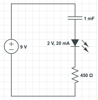
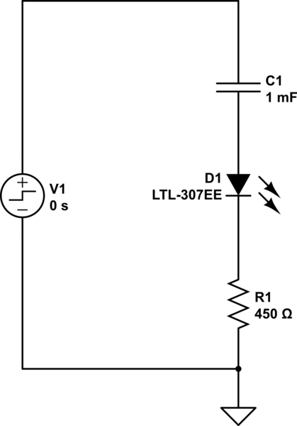
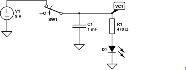
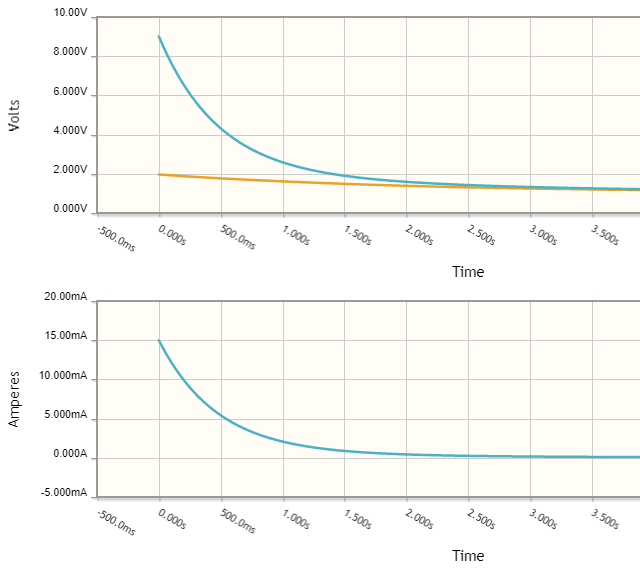
You could solve this circuit using KVL or a combination of simultaneous KCL equations. But @Transistor already showed you a better way to visualize the problem: by instead looking at it with the capacitor already charged and then watching it discharge into the remaining circuit rather than watching a discharged capacitor charging up. This does replace your question with a simpler but equivalent one.
I'm going to stick with that approach below.
There are three important model parameters for a forward-biased diode: its series Ohmic resistance \$R_\text{ON}\$, its saturation current \$I_\text{SAT}\$, and its ideality factor \$\eta\$. The Shockley diode equation (which every time I write his name makes me want to add some history because others deserve much they didn't receive), is:
$$I_\text{D}=I_\text{SAT}\cdot\left(\exp\left[\frac{V_\text{D}}{\eta\,V_T}\right]-1\right)$$
(Where \$V_T=\frac{k\,T}{q}\$ and is about 25-26 millivolts at room
temperature and where you must keep always in mind also that
\$I_\text{SAT}\$ itself is a strong function of temperature -- so
strong and so opposed to the direction of \$V_T\$ that its
temperature-dependent effects completely reverse what you might
imagine from the above equation.)
To include the effects of \$R_\text{ON}\$, we need to add the voltage drop across it, so that:
$$V_\text{D}^{'}=V_\text{D}+I_\text{D}\cdot R_\text{ON}$$
\$V_\text{D}^{'}\$ would be the voltage across the diode that we'd measure with a voltmeter.
Of course, we may as well now add the additional voltage drop caused by your external series resistance, \$R\$, since it's about the same thing. In this case, this voltage will be the capacitor voltage (taking @Transistor's concept to heart):
$$V_\text{C}=V_\text{D}+I_\text{D}\cdot R_\text{ON}+I_\text{D}\cdot R$$
All we've done now is to add in two Ohmic voltage drops, one internal to the diode and one external to it, in order to get the voltage across the capacitor. Let's solve the above for \$V_\text{D}\$ and plug that result back into the Shockley diode equation:
$$I_\text{D}=I_\text{SAT}\cdot\left(\exp\left[\frac{V_\text{C}-I_\text{D}\cdot R_\text{ON}-I_\text{D}\cdot R}{\eta\,V_T}\right]-1\right)$$
There's still a problem with this equation. The diode current, \$I_\text{D}\$, appears in two places. Let's solve it so that it only appears once.
But first, I'd like to define a special variable to represent the effects of the Ohmic parts and the thermal voltage, \$V_T\$, into one place. Doing so will reduce the equation clutter. I'm going to call it the Ohmic thermal current, \$I_{\Omega_T}=\frac{\eta\,V_T}{R_\text{ON}+R}\$. Given that, we have:
$$
\begin{align*}
I_\text{D} &= I_{\text{SAT}}\cdot \left(e^{^{\left[\frac{V_\text{C}}{\eta\:V_T}-\frac{I_\text{D}}{I_{\Omega_T}}\right]}}-1\right)\\\\
I_\text{D}+I_{\text{SAT}} &= I_{\text{SAT}}\cdot e^{^{\left[\frac{V_\text{C}}{\eta\:V_T}-\frac{I_\text{D}}{I_{\Omega_T}}\right]}}\\\\
\left(I_\text{D}+I_{\text{SAT}}\right)\cdot e^{^\frac{I_\text{D}}{I_{\Omega_T}}} &= I_{\text{SAT}}\cdot e^{^\frac{V_\text{C}}{\eta\:V_T}}\\\\
\frac{I_\text{D}+I_{\text{SAT}}}{I_{\Omega_T}}\cdot e^{^\frac{I_\text{D}}{I_{\Omega_T}}} &= \frac{I_{\text{SAT}}}{I_{\Omega_T}}\cdot e^{^\frac{V_\text{C}}{\eta\:V_T}}\\\\
\frac{I_\text{D}+I_{\text{SAT}}}{I_{\Omega_T}}\cdot e^{^\frac{I_\text{D}}{I_{\Omega_T}}}\cdot e^{^\frac{I_{\text{SAT}}}{I_{\Omega_T}}} &= \frac{I_{\text{SAT}}}{I_{\Omega_T}}\cdot e^{^\frac{V_\text{C}}{\eta\:V_T}}\cdot e^{^\frac{I_{\text{SAT}}}{I_{\Omega_T}}}\\\\
\frac{I_\text{D}+I_{\text{SAT}}}{I_{\Omega_T}}\cdot e^{^\frac{I_\text{D}+I_{\text{SAT}}}{I_{\Omega_T}}} &= \frac{I_{\text{SAT}}}{I_{\Omega_T}}\cdot e^{^{\left[\frac{V_\text{C}}{\eta\:V_T}-\frac{I_{\text{SAT}}}{I_{\Omega_T}}\right]}}\\\\
\operatorname{LambertW}\left(\frac{I_\text{D}+I_{\text{SAT}}}{I_{\Omega_T}}\cdot e^{^\frac{I_\text{D}+I_{\text{SAT}}}{I_{\Omega_T}}}\right) &= \operatorname{LambertW}\left(\frac{I_{\text{SAT}}}{I_{\Omega_T}}\cdot e^{^{\left[\frac{V_\text{C}}{\eta\:V_T}-\frac{I_{\text{SAT}}}{I_{\Omega_T}}\right]}}\right)\\\\
\frac{I_\text{D}+I_{\text{SAT}}}{I_{\Omega_T}} &= \operatorname{LambertW}\left(\frac{I_{\text{SAT}}}{I_{\Omega_T}}\cdot e^{^{\left[\frac{V_\text{C}}{\eta\:V_T}-\frac{I_{\text{SAT}}}{I_{\Omega_T}}\right]}}\right)\\\\
I_\text{D} &= I_{\Omega_T}\cdot \operatorname{LambertW}\left(\frac{I_{\text{SAT}}}{I_{\Omega_T}}\cdot e^{^{\left[\frac{V_\text{C}}{\eta\:V_T}-\frac{I_{\text{SAT}}}{I_{\Omega_T}}\right]}}\right)-I_{\text{SAT}}\tag{1}
\end{align*}
$$
Now you have a "simple" equation relating the capacitor voltage to the diode current (which is the same as the series loop current for all devices.)
Since \$I_\text{C}=I_\text{D}=C\cdot\frac{\text{d}\,V_\text{C}}{\text{d}t}\$
You can now rewrite things (keeping in mind the fact the rate of change in capacitor voltage will be negative for positive currents) as:
$$
\begin{align*}
-C\cdot\frac{\text{d}\,V_\text{C}}{\text{d}t} &= I_{\Omega_T}\cdot \operatorname{LambertW}\left(\frac{I_{\text{SAT}}}{I_{\Omega_T}}\cdot e^{^{\left[\frac{V_\text{C}}{\eta\:V_T}-\frac{I_{\text{SAT}}}{I_{\Omega_T}}\right]}}\right)-I_{\text{SAT}}\\\\
-\frac{\text{d}\,V_\text{C}}{\text{d}t} &= \frac{I_{\Omega_T}}{C}\cdot \operatorname{LambertW}\left(\frac{I_{\text{SAT}}}{I_{\Omega_T}}\cdot e^{^{\left[\frac{V_\text{C}}{\eta\:V_T}-\frac{I_{\text{SAT}}}{I_{\Omega_T}}\right]}}\right)-\frac{I_{\text{SAT}}}{C}\\\\
\frac{\text{d}\,V_\text{C}}{\text{d}t} &= \frac{I_{\text{SAT}}}{C}-\frac{I_{\Omega_T}}{C}\cdot \operatorname{LambertW}\left(\frac{I_{\text{SAT}}}{I_{\Omega_T}}\cdot e^{^{\left[\frac{V_\text{C}}{\eta\:V_T}-\frac{I_{\text{SAT}}}{I_{\Omega_T}}\right]}}\right)\tag{2}
\end{align*}
$$
Now you have an equation that tells you the rate of change in the capacitor voltage as a function of the capacitor voltage (eq. 2) and also the circuit current (eq. 1) at that moment! Between the two, you can iterate using tiny time steps to realize the diode current as a function of time. Or you could work on performing the integral indicated in eq. 2 to see if you could work out a closed function of time for the current.
But that's about as far as I want to go. Hopefully, it shows you both the complexity of the question as well as introducing the concept of the LambertW function in providing closed equation forms.
And now you know why engineers use reasoned methods for approximation. (Of course, that's the exact opposite of what a pure mathematician would do! They'd go for the solution and see if it lights up some new area of math for others! And they would not care in the least if any of it had practical significance. There's a big difference between the two types, in that regard.) For me, I just enjoy introducing the LambertW function to people. I think it doesn't get enough press.


