3
\$\begingroup\$

I have built a high voltage voltage-divider so I can use a low-cost single-ended HV supply at multiple DC output voltages simultaneously. The current delivery is very low at 50 uA max and the purpose of the circuit is to provide voltages for assessment of in-house HV measurement circuits. My HV supply goes up to 10 kV and I have used 5 x 250 MOhm resistors in series with a 5 GOhm resistor to GND. Theoretically this voltage-divider should produce voltages at 100%, 96%, 92%, 88%, 84% and 80% of the supply voltage.

The divider has been built using good quality components that are all rated for these voltages. The 5G resistor is Ohmite SLIM-MOX10803 with a maximum voltage of 20 kV and the 250 M resistors are Stackpole HVA series with a maximum voltage of 8 kV. So yes, the 10 kV should not go across a single one of the 250 M resistors, but the chain of 5 is perfectly fine. The resistors have been soldered together very nicely and are suspended between banana plugs that I will use to access the voltage output at each step of the divider. The components and HV supply are all nicely enclosed inside a plastic container. All components have been cleaned with isopropyl alcohol and given a final spray down with contact cleaner to remove any oil, flux, or other unwanted residue left over from assembly. The entire assembly "works" in that the HV supply always produces the correct output and does not seem to be over loaded by the voltage-divider, and there is no sign of arcing, corona, or discharge.

The signals are all DC and the voltages are measured using a 1:1000 HV probe (CalTest CT 4026, 200 MOhm input impedance) connected to a Rigol oscilloscope (MSO5074, 1 MOhm input impedance).

However, what I find is that the voltage divider does not work as intended. Instead of producing the % outputs listed above, I get 100%, 47%, 30%, 23%, 18%, and 15% of the maximum voltage. I do not have a mega tester to measure the resistance of the 250 MOhm resistors, but they are good quality components from DigiKey, and I am assuming that they are OK.

Can anyone please explain why this divider does not work as intended? What modifications should I make to improve it? Thank you.

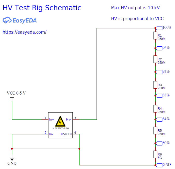
Schematic

\$\endgroup\$
7
  • \$\begingroup\$ AC or DC? And what is the purpose of this divider? Given the resistances it won't be supplying anything. \$\endgroup\$
    – Reinderien
    Commented May 18, 2021 at 3:13
  • \$\begingroup\$ I guess your measurement instrument is about 1 Gohm, put 0.1M in-series to gnd and measure that with a 10M probe. \$\endgroup\$
    – D.A.S.
    Commented May 18, 2021 at 3:14
  • 3
    \$\begingroup\$ Your problem is the meter you're using to measure the output. 250 MΩ is a lot, and a fair bit more than most cheap multimeters. \$\endgroup\$
    – Hearth
    Commented May 18, 2021 at 4:02
  • \$\begingroup\$ Thank you for the comments so far. I'll also edit the question to include this information, but the signals are all DC, the measurement instrument is a 1:1000 HV probe (CalTest CT 4026, 200 MOhm input impedance) connected to a Rigol oscilloscope (MSO5074, 1 MOhm input impedance). \$\endgroup\$ Commented May 18, 2021 at 4:12
  • \$\begingroup\$ What's the maximum rated voltage on those resistors???? Bet it's alot lower than 10k / 5 \$\endgroup\$
    – Kyle B
    Commented May 18, 2021 at 5:05

1 Answer 1

5
\$\begingroup\$

Your reduced measured voltages are consistent with the measurement point being loaded down by a resistance in the order of 200 Mohm.

The problem is not your voltage divider, but your measurement method. You need to use a higher impedance probe. Or you need to use a lower impedance divider. Or both. And/or to allow mathematically for your probe loading.

As you are using an oscilloscope for your voltage measurement, that suggests one technique of using a transfer capacitance. Charge a capacitor up on the tap you want to measure. Then apply the probe. The voltage will quickly fall (assuming reasonable capacitor values), but you'll capture the curve on your scope and be able to extrapolate back to the starting voltage, within the bandwidth / step response limits of your probe.

Another approach is to use a field mill, which is a voltage measurement instrument with an infinite input impedance. As your supply is variable, you'll be able to calibrate the field mill using the supply itself. First take a reading of the tap on the mill, then take a reading of the supply, and reduce the supply voltage until the field mill gives you the same reading.

\$\endgroup\$

Your Answer

By clicking “Post Your Answer”, you agree to our terms of service and acknowledge you have read our privacy policy.

Not the answer you're looking for? Browse other questions tagged or ask your own question.