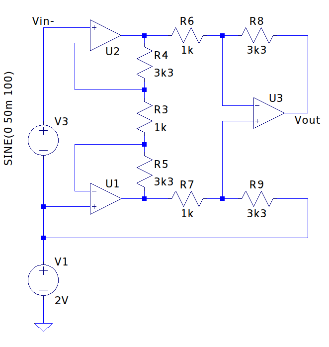
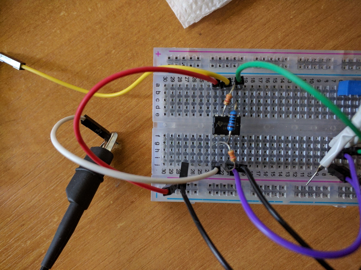
I'm trying to build an instrumentation amplifier, following the schematic attached below. I got two LM358P chips, signal generated by a computer sound card and an oscilloscope. The schematic and overall assembly attached below.
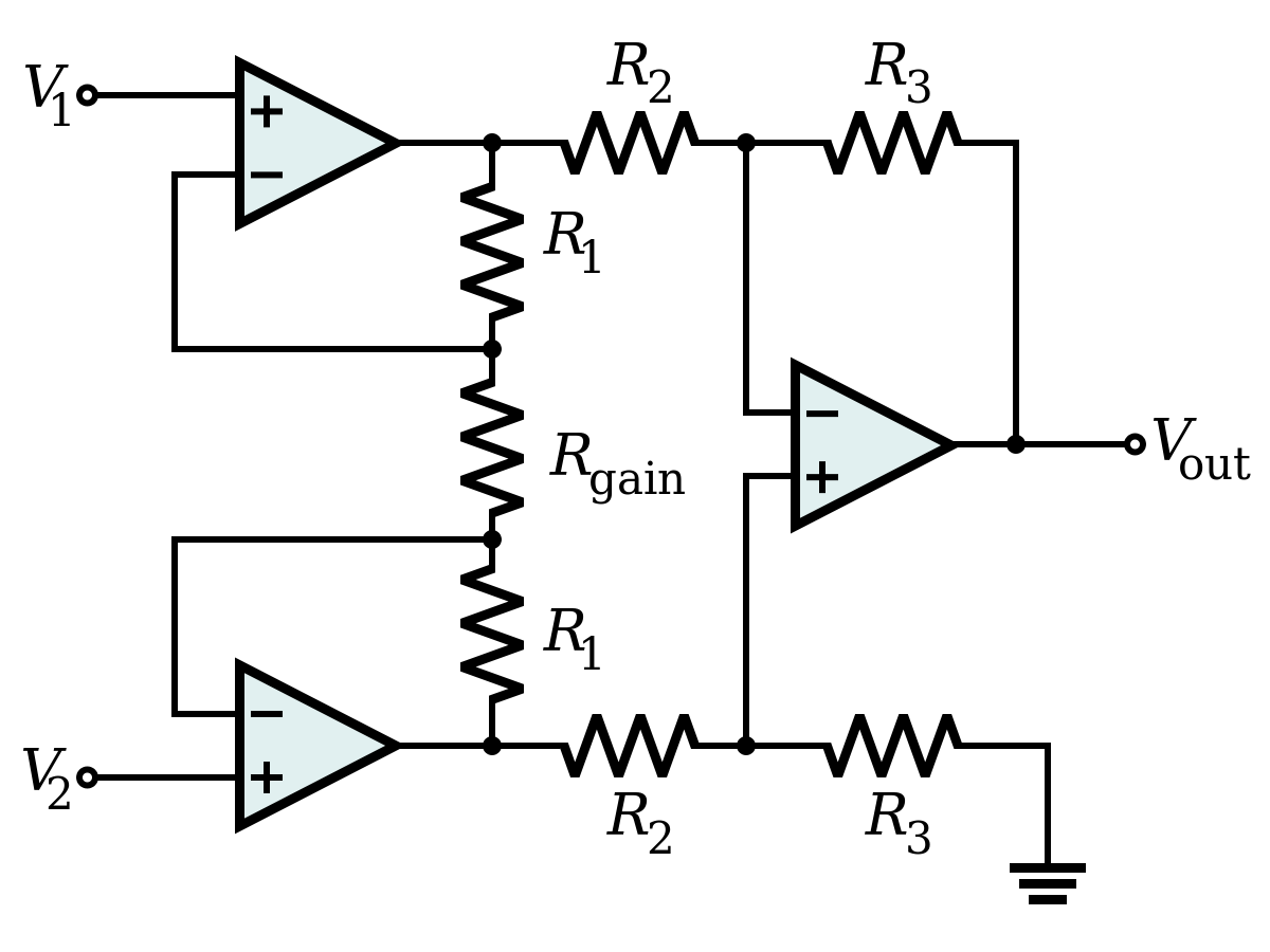
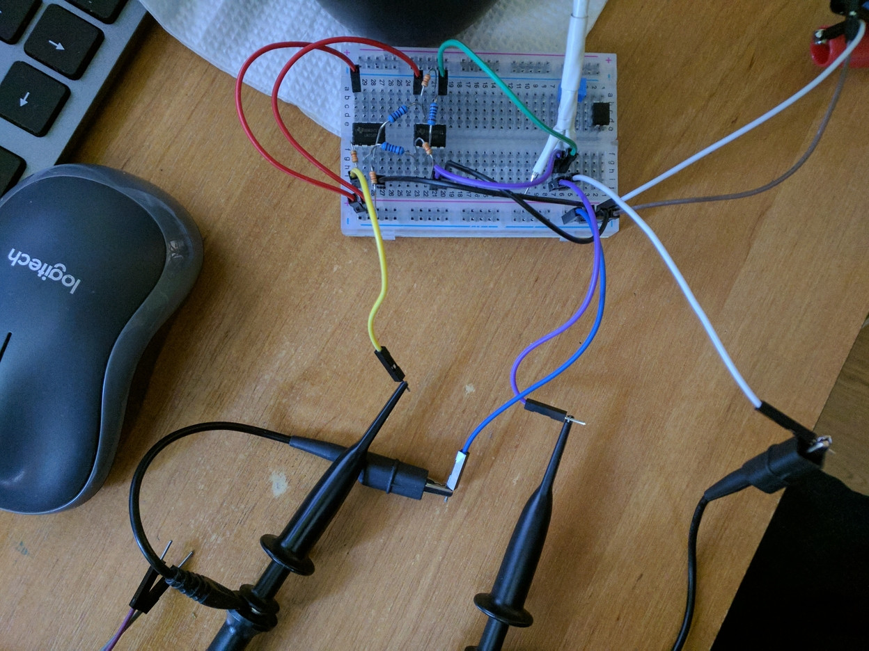
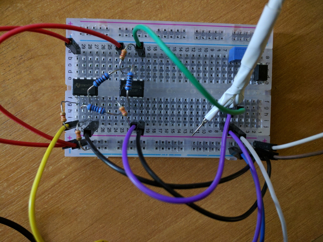
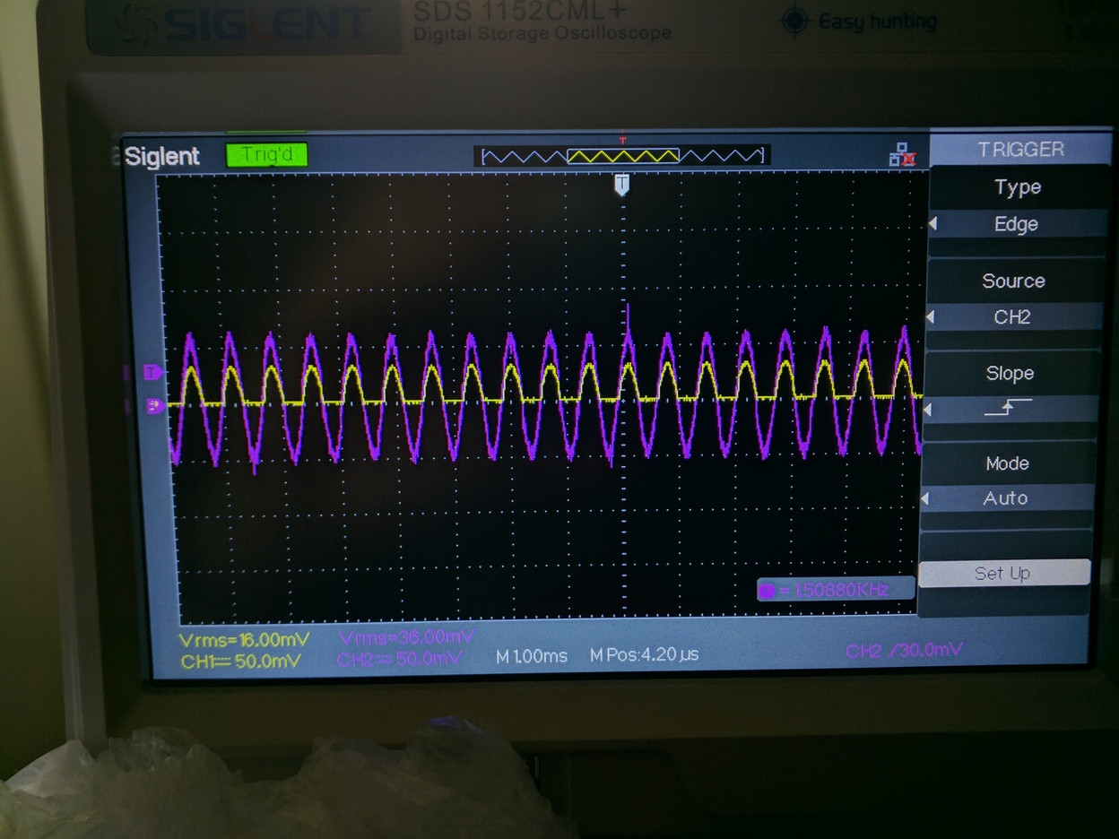
I got two types of resistors here. The blue ones are 1KOhm, the orange are 3.3KOhm. So that Rgain and R2 are 1kOhm, R1 and R3 are 3.3kOhm. I was trying to get the connections clear on the photo, and here's the best I could get. According to formulas on Internet, I should get amplification of around 10 times. Or at least any. But what I see on the scope is the same signal with values below zero being cut (ch1 is output, ch2 is input).
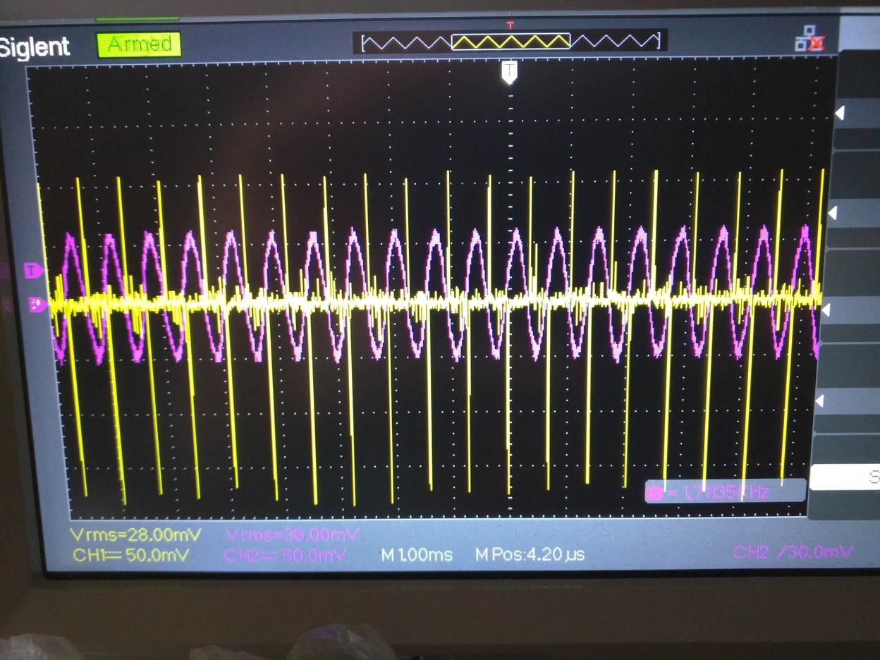
What's even more confusing, if I don't use the second stage of the amplifier and monitor the signal before R2 - it goes even more weird.
I assume I'm taking measurements wrong. Or my assembly is wrong. Could someone explain what is going on and why this whole thing does not work?


