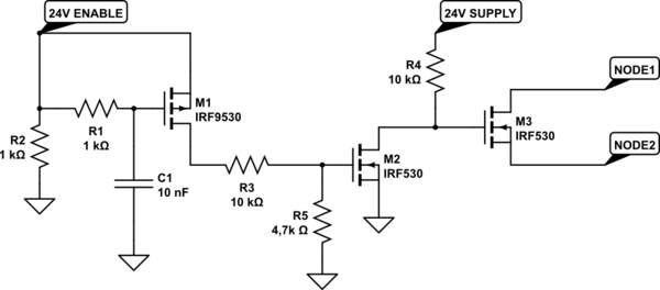
I'm using this circuit:

simulate this circuit – Schematic created using CircuitLab
The circuit is powered by "24V" , "24V ENABLE" is the trigger. The circuit should act like a one-shot signal (or single impulse) that is OPEN for about 100us (between NODE1 and NODE2) when a transition from 0V to 24V occurs on ENABLE. It should then stay closed for the rest of the time.
When thr trigger was generated by a push button on the bench all worked well. Now that I've moved to the real application that uses an opto-relay to trigger the circuit, the circuit doesn't work for values lower than 100nF, this mean impulse time longer than 500us.
This happens because the voltage on the opto-relay rises very slowly and this rising speed is comparable to C1 charging speed. What happens is that M1 never triggers. With higher values of C1 the charge slows, but also the impulse time that should not exceed 100us.
Do you have suggestions on how to avoid this applying changes to this circuit?
