4
\$\begingroup\$

The gain of transistor Q1 was previously calculated in this post
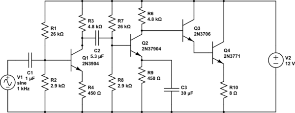
schematic

simulate this circuit – Schematic created using CircuitLab

It was found to have a gain of about 2.92. Now I change the parameters as below:
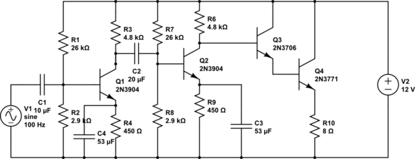
schematic

simulate this circuit

The DC gain of both Q1 and Q2 is roughly 270. When I calculate the gain calculated according to the formula in the above link, I get

$$A_v=\frac{R3||R7+R8||\beta_{Q2}(r_e'+X_c)}{X_c+r_e'}=28.65$$

However, my simulation gave a gain which is about 40.

After that I recalculate again by considering the real part and the imaginary part as below I get:

$$A_v=\frac{R3||R7+R8||\beta_{Q2}(r_e'+\frac{1}{jwC})}{r_e'+\frac{1}{jwC}}=\frac{R3||R7+R8||\beta_{Q2}(22.72-30j)}{22.72-30j}=\frac{1515-181j}{22.72-30j}=40.55$$

That is much closer to the simulation value.

Do we calculate in such a way or it just by sheer luck using the wrong method to get the value which is closer to the simulation value? After all, this is calculating the impedance as view by the AC signal right?

I also calculated the gain for the first diagram by considering the imaginary part and real part. I got the gain as 2.8 which is not far from the gain of 2.9

\$\endgroup\$
5
  • \$\begingroup\$ In the example above, \$r^{'}_{e} = 22.72\Omega\$ and \$|X_c| = 30\Omega\$ are quite close to each other and you cannot neglect the smaller one. What were the values of these variables in the situation where you got values which were in agreement with the simulation ? I think \$r_e\$ was smaller than \$|X_c|\$ and didn't contribute much to the combined impedance. IMO, the complex impedance method is the correct way. \$\endgroup\$
    – AJN
    Commented May 28, 2021 at 13:34
  • \$\begingroup\$ I agree with @AJN. I've done these calcs where the capacitor is taken in quadrature with resistive impedance. (Note also that \$r_e^{'}\$ itself is a result of a derivative of the Shockley equation.) But these stages aren't used anymore and, in fact, never were used that much even when BJTs cost lots of dollars each. They are academic. Especially today. Besides, almost any discrete BJT design will use forms of global NFB, which deals with part variations extremely well. Also, almost by definition, the series capacitor impedance between stages is "mostly negligible." Or should be. \$\endgroup\$
    – jonk
    Commented May 28, 2021 at 13:52
  • \$\begingroup\$ A completely discrete BJT design is almost never seen, as opamps usually do all the lifting in between the 1st stage and the final stage. BJTs (and JFETs) are still important for certain low noise pre-amplifier stages, where a specific type of input transducer is being brought into the system. And discrete BJTs (and JFETs and MOSFETs) are still important for output stages that require 2-quadrant, high voltage or high current output compliance ratings. But opamps do most everything in between. \$\endgroup\$
    – jonk
    Commented May 28, 2021 at 13:58
  • \$\begingroup\$ Even if you were to decide on an entirely all-BJT design, you'd be far, far more likely to choose an approach that looks like (but would need a few added components to deal with BJT variations) the internals of an LM380 or LM386, where crafted NFB is used to set the voltage gain and the BJTs are put to far better use than these CE stages, which tend to also require largish and expensive capacitors. And finally, you should not use a grounded capacitor CE stage to get high voltage gain unless you also use a lot of NFB to correct the distortion that stage has. \$\endgroup\$
    – jonk
    Commented May 28, 2021 at 14:02
  • \$\begingroup\$ There are too many better ways of arranging BJTs. Even if you were forced into using this particular form of CE stage, open-loop gain, etc., you'd probably use a bootstrapped version in order to improve the input impedance by at least an order of magnitude, if not more. The cost is one small capacitor and one resistor. And yet there are still better ways to use your BJTs, even then. +1 on the question, though! (Sometime, when you get a chance, lay out the full equations and then do a sensitivity analysis on it and see what the dominant problems are with calculating a specific gain value!) \$\endgroup\$
    – jonk
    Commented May 28, 2021 at 14:05

1 Answer 1

1
\$\begingroup\$

The method demonstrated in the post mentioned is incorrect. Taking the full (complex) impedance into account is always more correct.

In some cases you can end up with a good approximations but my take on it is that it will be mainly luck that it turns out negligible somewhere. However, if you cannot clearly define where such "negligible"-ness appears, you should not make the equivalence as you have demonstrated with your second example.

\$\endgroup\$

Your Answer

By clicking “Post Your Answer”, you agree to our terms of service and acknowledge you have read our privacy policy.

Not the answer you're looking for? Browse other questions tagged or ask your own question.