1
\$\begingroup\$
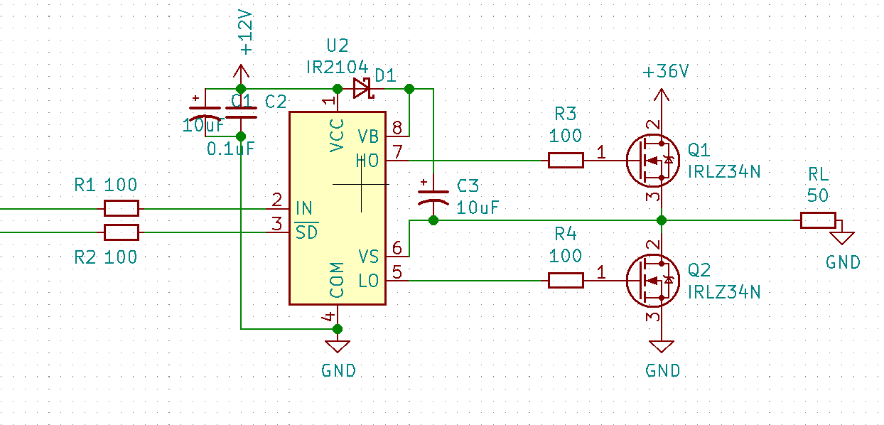
  • I'm using IR2104 to drive two N-MOSFET, 2 kHz with very low duty. IR2104 is a half-bridge driver with fixed deadtime:

enter image description here

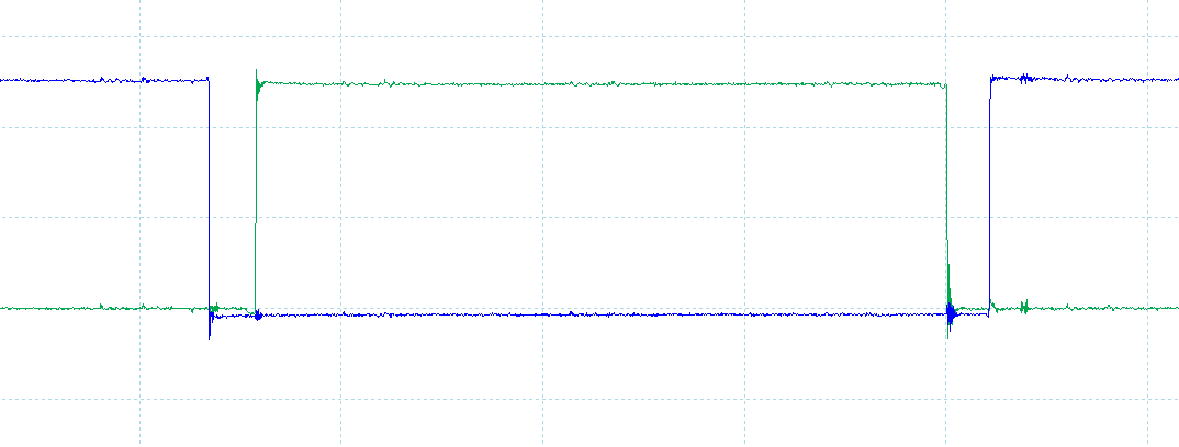
  • This is the gate driver output without MOSFET:

enter image description here

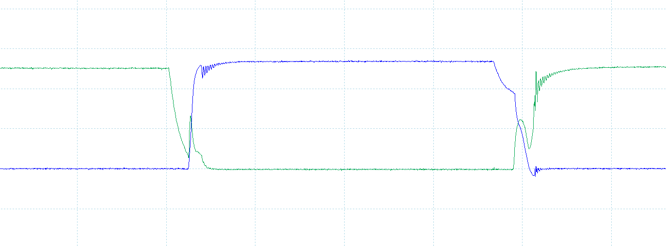
  • This is the MOSFET gate when working:

enter image description here

  • As you can see, it's taking longer for the MOSFET ti shut down than the deadtime.
  • Why the MOSFET won't shutdown immediately and what can I do to make it shutdown within deadtime?

Thanks in advance!

\$\endgroup\$
5
  • 6
    \$\begingroup\$ Those 100 ohm gate resistors will slow things down considerably. It's not uncommon to place diodes in parallel to those for fast turn-off. (Cathode pointing to the gate driver IC). \$\endgroup\$ Commented May 29, 2021 at 7:34
  • 1
    \$\begingroup\$ @Unimportant What about 10K pull-down resistor, will that work ? \$\endgroup\$
    – 7E10FC9A
    Commented May 29, 2021 at 7:36
  • 1
    \$\begingroup\$ @Unimportant it worked, thanks ! \$\endgroup\$
    – 7E10FC9A
    Commented May 29, 2021 at 10:08
  • \$\begingroup\$ what is the purpose of the 100 Ohms resistors? Instead you should add a gate driver to charge and discharge the capacitances in you mosfet as fast as necessary. \$\endgroup\$
    – arnisz
    Commented May 29, 2021 at 10:37
  • \$\begingroup\$ @arnisz The IR2104 is a half bridge gate driver. For a low frequency, such as the mentioned 2 kHz, those 100 ohm resistors are not unreasonable. They provide slowdown and damping which reduces oscillation and ringing. \$\endgroup\$ Commented May 29, 2021 at 10:55

1 Answer 1

0
\$\begingroup\$

I recommend making two changes: reduce the gate resistance and add a diode across the gate resistors. 100R resistors may be a bit too large, so try 10R or thereabouts. Adding a diode to help discharge the gates of the MOSFETs also helps turn them off faster. Also, you may have noticed that, when the upper MOSFET(Q1) turns on, the gate of the lower MOSFET(Q2) gets pulled high. This is caused due to the reverse transfer capacitance of the MOSFET (Cdg).

When Q1 turns on, the node between the two MOSFETs suddenly gets pulled high. Due to this sudden appearance of a voltage at that node (to with the drain of Q2 is connected), the gate of Q2 gets charged through the reverse transfer capacitance of Q2. A lower gate resistor or a diode will help suck this unwanted current into the driver and preventing the gate from being pulled up.

It is important to ensure that both MOSFETs of the halfbridge switch cleanly with a clear deadtime, or else there will definitely be a cross-conduction, which can stress the MOSFETs and cause a dip in the power supply.

\$\endgroup\$

Your Answer

By clicking “Post Your Answer”, you agree to our terms of service and acknowledge you have read our privacy policy.

Not the answer you're looking for? Browse other questions tagged or ask your own question.