1
\$\begingroup\$

I was reading some articles online where it talked about this kind of RC oscillator.

I just want to clarify some caveats about this circuit:

From: https://learnabout-electronics.org/Oscillators/osc31.php it says: "even though using four filters does give slightly better frequency stability" while this article says: "By cascading three or even four RC stages together, the stability of the oscillator can be greatly improved."

I see a contradiction here. Which article is right about having better stability with 4 stages rather than 3? Does having 4 stages allow for greatly improved stability or just slightly better?


The second thing that I wanted to clarify/know about is the loading effect of the RC stages and its performance and stability/reliability of the circuit. It says here:

But because this formula is based on calculations for individual filters, it does not fully take into account the effect of connecting the filters in cascade, which causes of one filter to be 'loaded' by the input impedance of the next, as shown in Fig.3.1.3, where the input impedance of filter 2, made up of the reactance (XC) of C2 and the resistance of R2 effectively changes the value of the output resistor of filter 1 (R1) as they are effectively connected in parallel with it.

Could someone go into more detail about this and talk about how it affects the performance and stability/reliability of the circuit?

\$\endgroup\$
1
  • \$\begingroup\$ A correction to @nomenclature's answer: if you use 4 sections then an extra 1° of phase introduced to the system, will change the oscillation frequency by −0.259892/180⋅f0. (I forgot that the angles were measured in radians). That's a much more reasonable 0.14% per degree, instead of a patently absurd 25.9% per degree (!). (Moderators, sorry about the mess. Please sort it out for me. I can't register on my privacy VPN) \$\endgroup\$ Commented Jun 8, 2022 at 1:22

3 Answers 3

6
\$\begingroup\$

Have a look at the TI publication "Sine-Wave Oscillator":

https://www.ti.com/lit/an/sloa060/sloa060.pdf

It's an excellent reference for designing phase-shift oscillators with RC components. I'll be referring to that in my answers.

Why does adding more stages improve frequency stability?

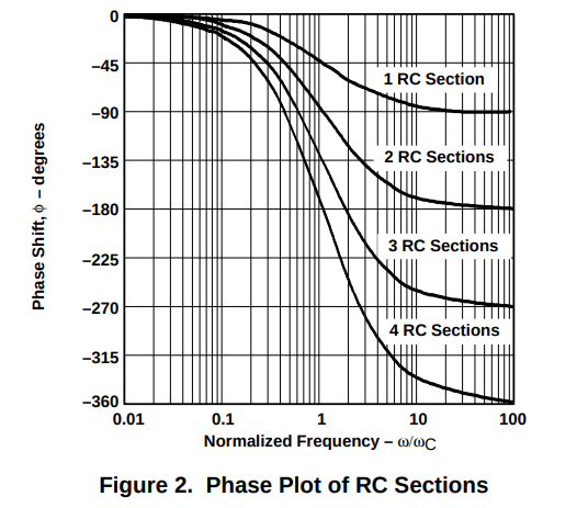
Figure 2 from the paper shows plots of phase shift \$\phi\$vs. frequency \$\omega\$ for different numbers of stages. The stability of the oscillator is related to the derivative \$d\phi/d\omega\$ at the point where \$\phi\$ equals 180 degrees: enter image description here

Adding more stages makes the slope at that point steeper which is better for stability. For instance, consider some noise which introduces a 1 degree phase shift into the system. In a four-stage oscillator the change in \$\omega\$ will be a lot smaller than it would be in a three- or two-stage system.

Why is four stages preferred over more stages like 5 or 6?

It has to do with a lot of practical matters:

  1. More stages means more components, i.e. high cost, more board space, etc.
  2. To reduce loading effects you often want to include op-amps between the stages as pictured in Fig. 16:

enter image description here

Op-amps conveniently come in 4 device packages. If you used 5 or 6 stages you might be wasting devices.

  1. If you use four stages then two of the stages will be 90 degrees out of phase with each other -- i.e. like a sin and cos pair also called a quadrature pair. Such a pair of signals are very useful in signal processing applications. With 3 stages you can get a phase difference of 60 or 120 degrees and with 5 stages multiples of 36 degrees. You can get a quadrature pair with 6 stages but you have the extra components and cost to consider.

See Section 8.4 in the TI publication for an example of a four stage oscillator producing quadrature signals.

  1. Four stages turns out to be good enough for most applications.

What is loading and why should I be worried about it?

When we analyze an RC-filter we usually describe it by saying it has a certain cut-off frequency and a certain phase-shift graph. However, that characterization is only valid in the absence of any other circuitry. Once it is in a real circuit it's performance will be influenced by the following stages.

This SE answer delves into the math of the loading effects of multiple RC-stages:

https://electronics.stackexchange.com/a/220065/95488

The most common way to mitigate the effects of loading is to use op-amps to buffer each stage as shown in the figure above. See section 8.3 in the TI publication for more advice on how to do this.

\$\endgroup\$
3
  • \$\begingroup\$ What if I want to generate a very high frequency with my circuit, like in the GHz range? Then certainly the op-amp won't work since it does not operate in that range. Are there any other options for high frequencies? \$\endgroup\$
    – Shocked
    Commented Jun 2, 2021 at 10:27
  • 1
    \$\begingroup\$ For higher frequencies LC-tanks are used followed by crystals followed by PLL-multipliers. At a certain point you just buy chips/modules, e.g.: mouser.com/Passive-Components/Frequency-Control-Timing-Devices/… \$\endgroup\$
    – ErikR
    Commented Jun 2, 2021 at 12:07
  • \$\begingroup\$ Thanks, I will keep that in mind. \$\endgroup\$
    – Shocked
    Commented Jun 2, 2021 at 20:20
1
\$\begingroup\$

Which article is right about having better stability with 4 stages rather than 3?

They both say basically the same thing. One says "slightly better" the other says "greatly improved".

The reality is that stacking RC stages only decreases the frequency rolloff rate of the filter, and in real circuits doesn't do much to improve the quality factor (or the oscillation frequency) because of parasitics.

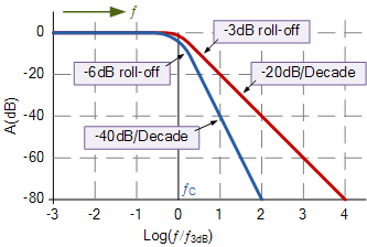
You can see this in the diagram below, one RC filter gives a -20dB/Dec rolloff in slope, two gives -40dB/Dec. This filter is used to regulate the oscillator, adding more poles doesn't do much to actually change the frequencies that feed back into the oscillator (pass band)

enter image description here
Source: https://www.electronics-tutorials.ws/filter/second-order-filters.html

As far as loading goes, the more filters you add in series with real components, the worse your pass band gets. The way to get around this is to use active filters (like the buffered phase shift oscillator in the link above), but also uses more energy as the amplifiers regulate the voltage on the components to give an output similar to what ideal components (components that don't have parasitic resistance, inductance, capacitance) .

\$\endgroup\$
3
  • \$\begingroup\$ So at the end of the day, having a 4th RC stage is somewhere in between slightly and greatly better, but nonetheless, improves the circuit stability? Also, when you say "the worse your passband gets", do you mean that you can only output a certain band of frequencies with this circuit like a bandpass filter or notch filter? I am fixated on the word "passband" in your answer and not the loading effect at this moment. I thought this circuit can output "any" frequency? \$\endgroup\$
    – Shocked
    Commented Jun 1, 2021 at 23:03
  • 1
    \$\begingroup\$ An oscillator amplifies resonant frequencies, this means you have to select frequencies to be resonant. If you place an amplifier in feedback, it will amplify whatever frequencies are in the feedback loop, thus it becomes necessary to filter out some of the frequencies you don't want and select the ones (or one) frequency you do want to amplify. \$\endgroup\$
    – Voltage Spike
    Commented Jun 2, 2021 at 3:18
  • 1
    \$\begingroup\$ No - there is no resonant effect in RC-lowpass sections. The main point is: The frequency with a total phase shift of -180deg can fulfill the oscillation condition (with an inverting amplifier). \$\endgroup\$
    – LvW
    Commented Jun 2, 2021 at 9:18
1
\$\begingroup\$

I wanted to understand why the slope affects frequency stability too.

@ErikR gave an excellent answer, but I would have benefited from a more explicit explanation. Here it is for the benefit of others.

The system will oscillate at the frequency at which a signal accumulates 180° as it passes through the feedback loop.

If some parasitics in the system, for example, add an additional phase shift of 3° to signals passing through the system, the frequency of oscillation will shift, and will now be the frequency which accumulates (180-3)=177° when it passes through the rest of the feedback loop.

If the slope at 180° is large, the new frequency will be closer to the nominal frequency, compared to what it would be if the phase transition was more gradual.

And of course "more stages=sharper curve". Whether 4 stages are substantially better than 3 depends on requirements. But assuming you use a quad package, you might prefer to get an extra op-amp for free if you have a use for it, and if you don't - you might as well use it to improve frequency stability some more.

Here's what I calculated for the slope at the \$\frac{\pi}{n}\$ point:

n  1/(dphase/dfreq)
===================
2  -1
3  -0.377491
4  -0.259892

So for example, if you use 4 sections then an extra 1° of phase introduced to the system, will change the oscillation frequency by \$-0.259892 \cdot f_0\$ (i.e. it will lower it, as one would expect), where \$f_0\$ is the nominal frequency.

  • Using 4 sections reduces the error by 31.2% compared to using 3 sections.
\$\endgroup\$

Your Answer

By clicking “Post Your Answer”, you agree to our terms of service and acknowledge you have read our privacy policy.

Not the answer you're looking for? Browse other questions tagged or ask your own question.