I am a newbie and my first post. So please excuse my ignorance in advance.
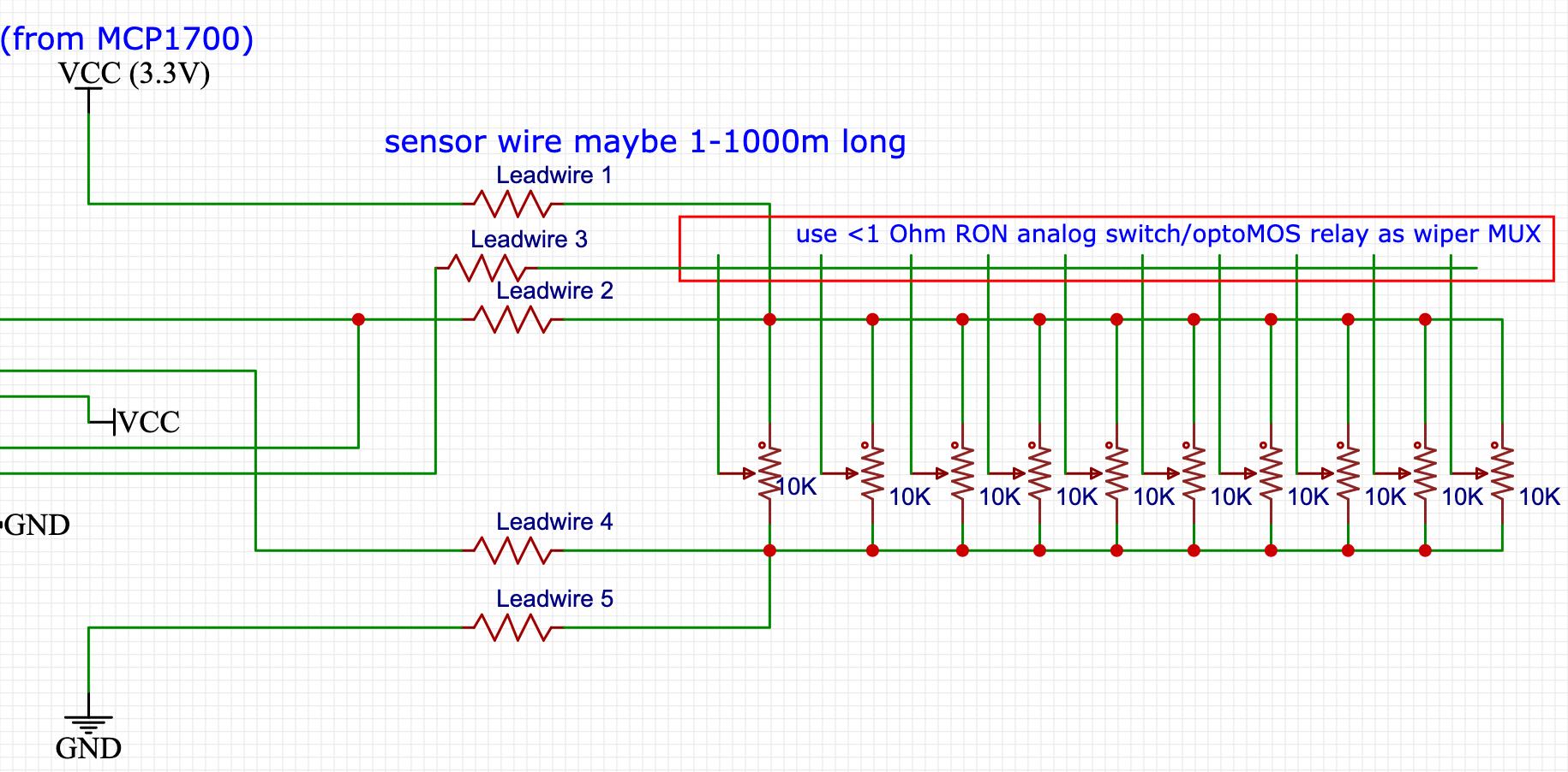
My project is to create a handheld readout to read potentiometer(s) (10K linear precision pot) with minimum 10000 steps accuracy. The unit should also be able to accommodate for lead wire resistance of cable from the readout to the potentiometer. Ultimately the readout should be able to read upto 10 similar potentiometers wiper values when these pots are connected together with the same excitation wires. Maybe i will use some analog switch with Ron <1 Ohm as a MUX to read sifferent values. thats something after I solve my initial issue to read 1 single 10kOhm pot with desired precision and suitable protection from short circuits
The device should display the current pot's wiper value in a LCD display. The unit will be battery powered and will be used as a handheld portable readout.
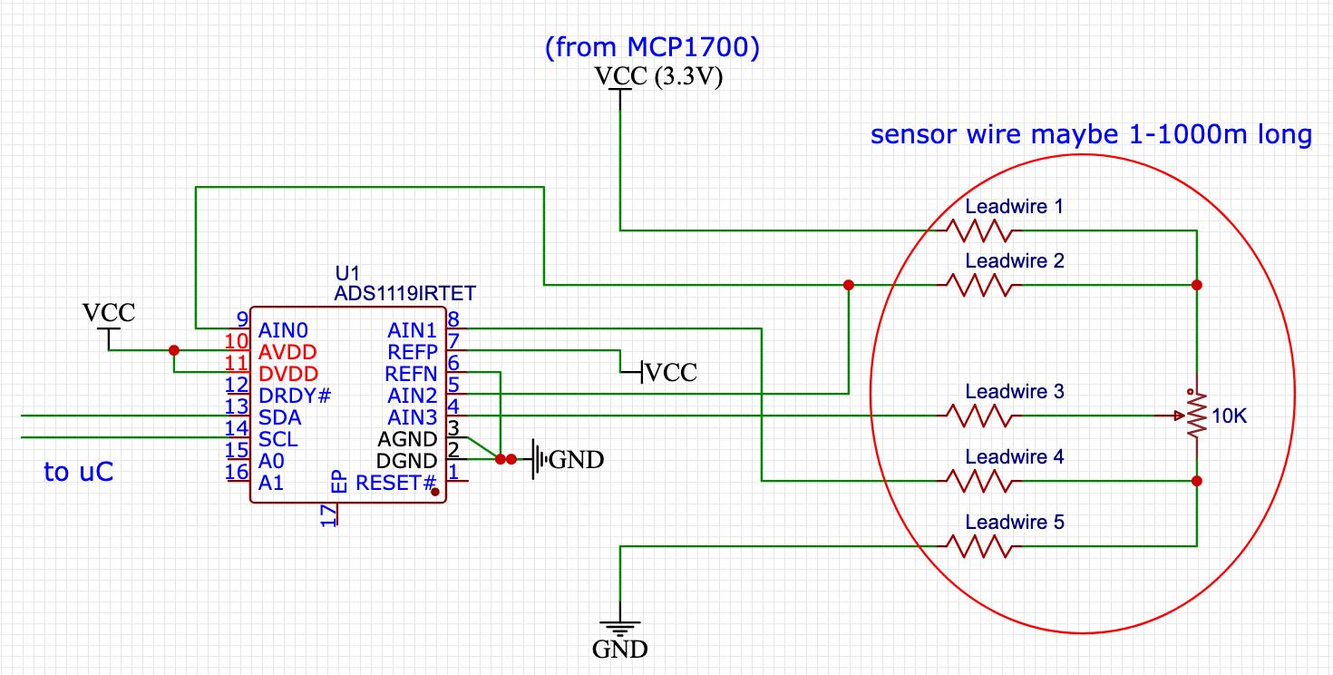
I managed to create a crude prototype using arduino nano, ADS1115 ADC and external LCD. Using ADS115 i was able to get a relatively stable reading from a single potentiometer (without any lead wire compensation). I used some running averages to smooth out any fluctuations. The ADS1115 was setup to read 8SPS as the sampling speed does not need to be super fast for my case. Also I read that lower sampling rate removes/reduces errors & noise. I provided 5V from nano to excite the pot and setup the PGA to the default 6.144Volts to measure the wiper voltage between 0-5V. I calculated the wiper position by taking a differential voltage measurement between the excitation & GND divided by wiper and GND. does this mean I was basically doing single ended measurement? Maybe should have done diff measurement between excitation-GND and excitation-wiper and take its ratio???
I understand that since ADS1115 has no external reference, in my case it's better to use an ADC with external reference to remove the excitation voltage fluctuation error. Hence I've decide to use ADS1119 (gets me 15bits resolution and omits the noise in my supply). Its got 2 x differential channel, external reference voltage & i2c to interface with atmega328p. I have also decided to use MCP1700 3.3V LDO to power the circuit (low quotient current for mostly sleeping battery powered readout, stable(ish) at around 2% & very low Dropout Voltage). Ultimately the ATMEGA328p will use 8MHZ crystal and will use 3.3V supply and should not require more power tan is supplied by MCP1700. I plan on creating my own pcb with these parts . The pcb will also contain some keypad (1x4 membrane keypad to toggle through the menu and a MUX to read between 1-10 pots). It will most likely be designed around ATMEGA328p or ATMEGA2560 (haven't finalised this part, depends on the requirement GPIO & power saving features- open to sugestions).
Now my main questions are:
1- In my case is this ADS1119 the best way to read a potentiometer? Or whats a proper way to read a potentiometer ?
2-Do I need seperate LDO for excitation? maybe precision voltage reference source? can precision reference even be used to excite the potentiometer(s)? OR voltage reference doesn't matter as long as I use the same source as external Vref for ADC and excitation for potentiometer? What is a proper excitation voltage in my case? is 3.3V enough or is bigger better, 5V??
3- How do compensate for lead wire resistance of my wires connecting my ADC to my potentiometer?
 (in this schematic please excuse that I am missing decoupling caps in the ADC)
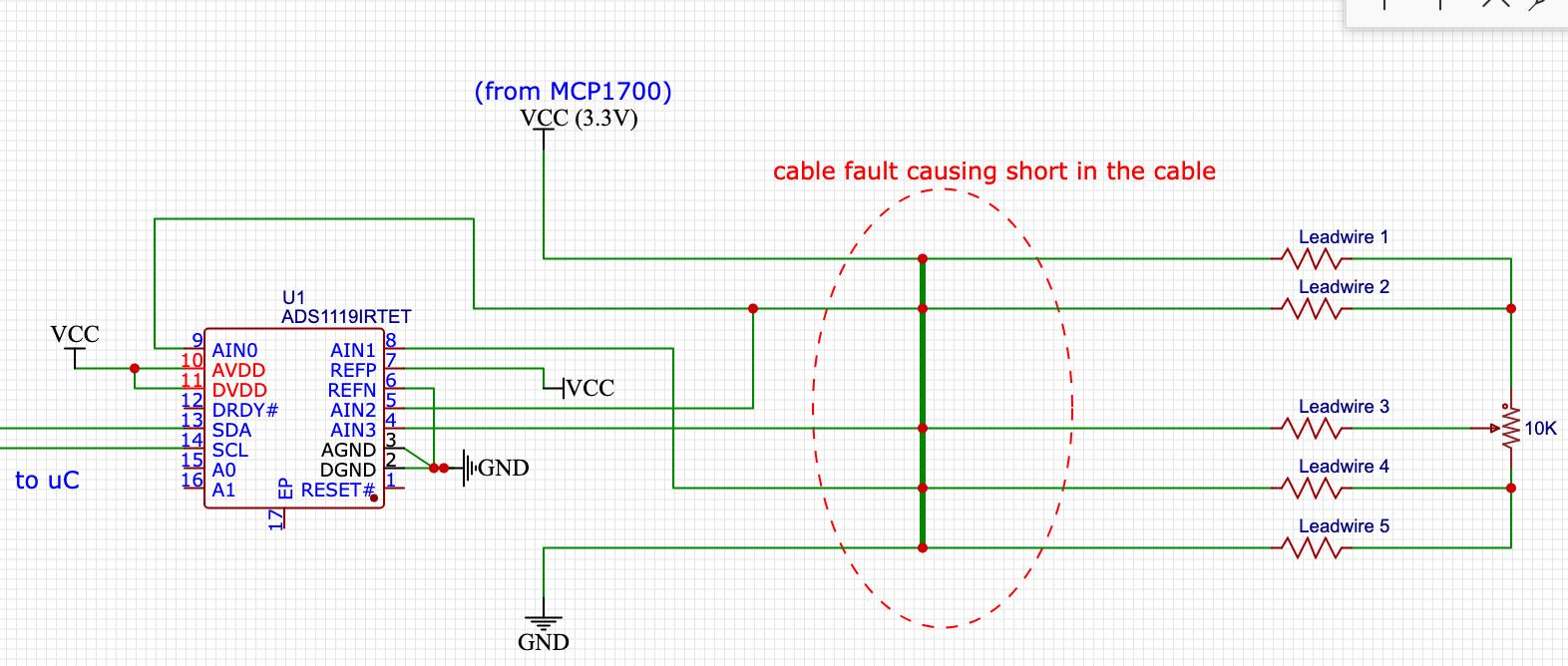
4-In case there is a fault in the wire between my readout and the potentiometer, how do I prevent a short circuit between the excitation voltage and ground damaging my unit and display an error/fault in LCD? This will affect the battery life and possibly damage my LDO,ADC?? How to identify if there is short in the cable?? how to create protection circuit to prevent this and not affect my ADC measurements? This part I don't even have any idea on how to solve it. :(

5- to save power, is it better to use a relay to only supply excitation voltage to the potentiometer when its being measure? Or since this is a readout only used when you want to measure the pot, then maybe I don't need to worry about this part. Second thoughts maybe this relay controlled excitation only makes sense when it's acting as a datalogger which is constantly connected to the sensor.
6- Ultimately the readout should be able to read upto 10 wiper value from 10x 10K pots. Preferably not using rotary switch but a multiplexer which can be sued to select the wiper using a keypad button press.

In this case when there are 10x pots, the effective resistance becomes 1K from 10K. So the unit should be optimised to excite resistance between 10K (single pot) and upto 1K (10x pots) or anywhere in between without any significant change to the battery life,performance?? This is the final step.
Please let me know if I am missing any other info.
