1
\$\begingroup\$

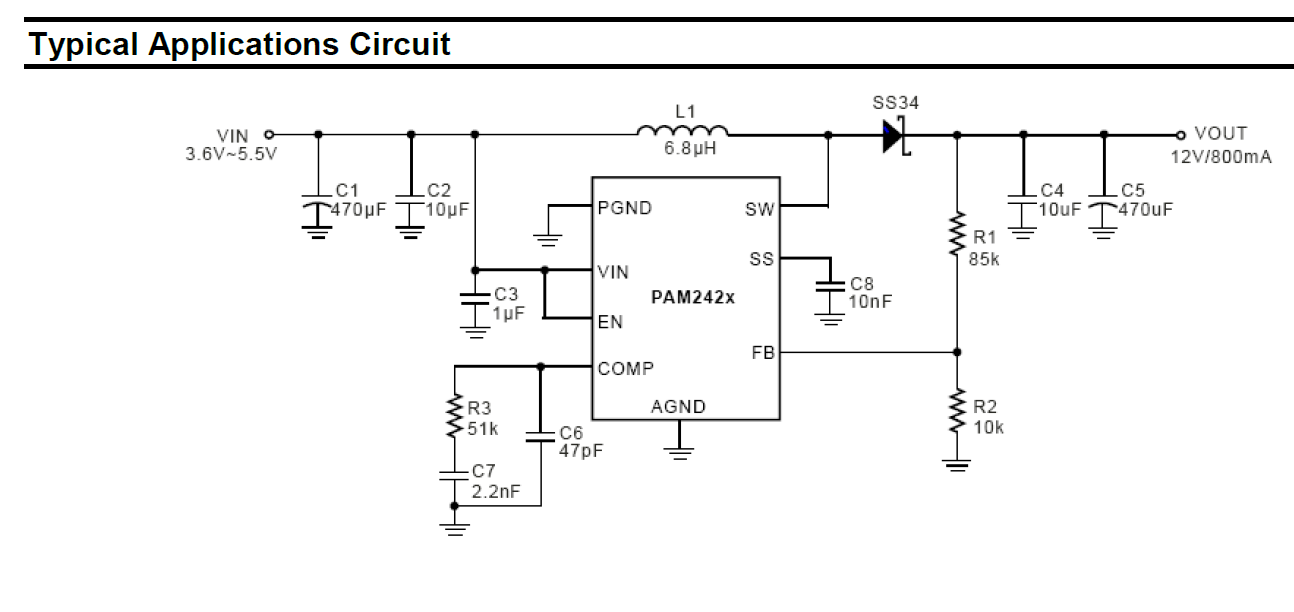
I'm trying to a boost conveter PAM2423 which workd at 520kHz for the first time(using a high quality breadboard from jameco for prototyping) following the manufacturer ref schematic:

enter image description here

My Setup:

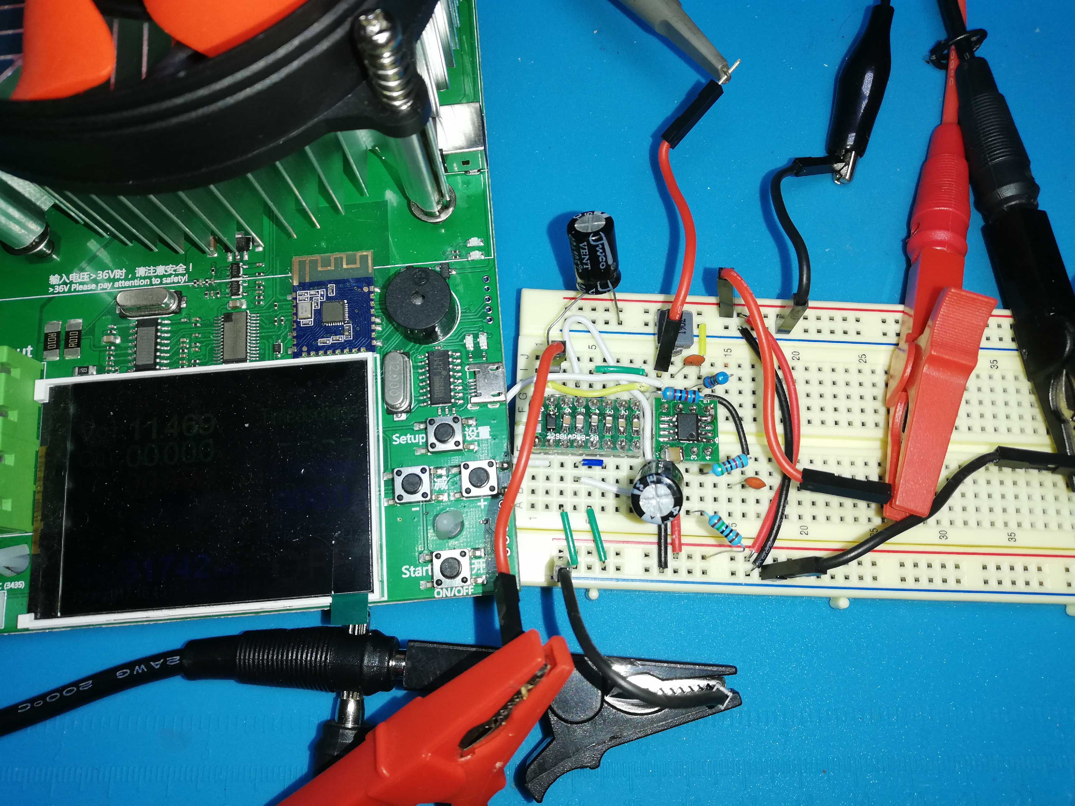
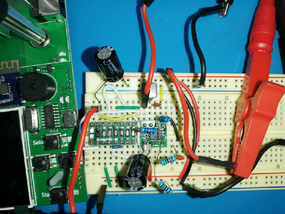
enter image description here

enter image description here

I've soldered a 10uF input ceramic capacitor directlly to the chip

and unlike the manufacturer schematic I've added a 150OHM resistor between the VIN and EN pin because I've suspected shorting it directly burned the last IC. I'm using the PA4341.682NLT 6.8uH 4.5A as the inductor if that matters(of course connected as closely as possible to the IC's output)

The PGND and AGND along with the button pad are connected to the same GND.

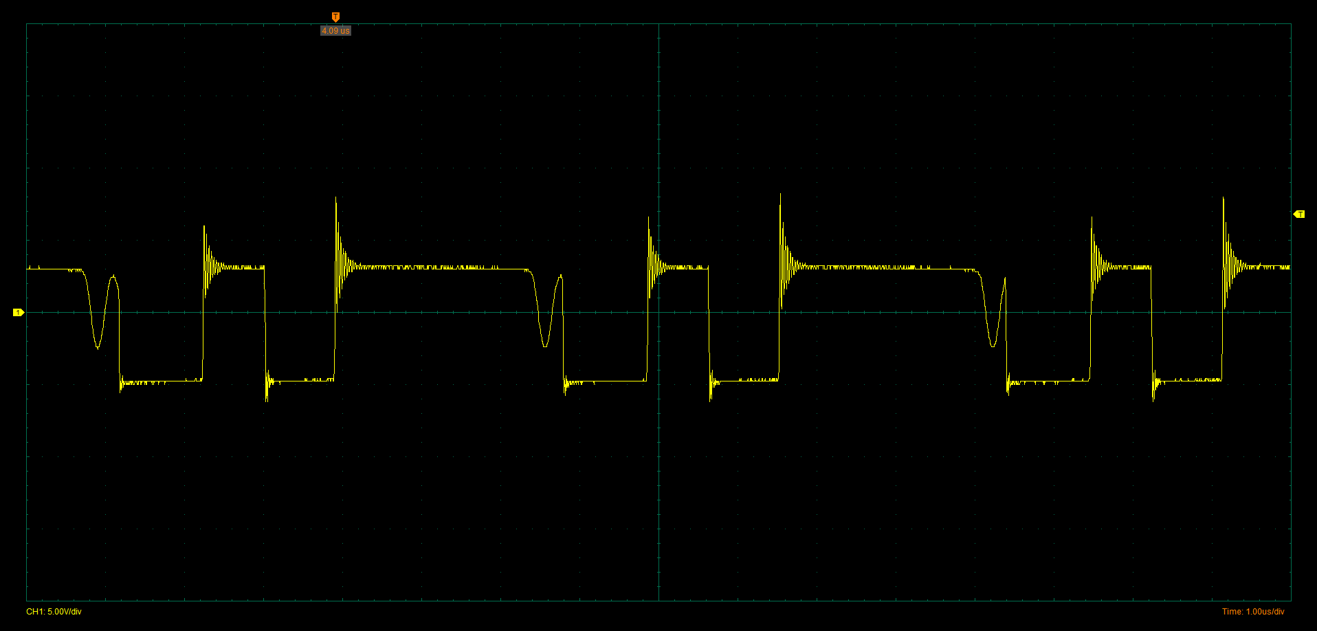
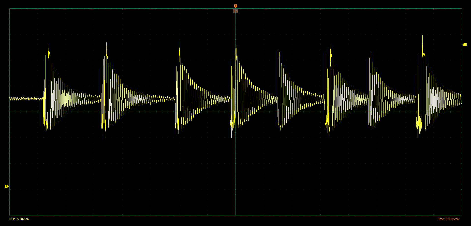
Here is the scope output connected between SW Pin of the IC and GND connected to an E-load @ CC 0.1A with VIn = 4.2V and Average (not that stable) output voltage of 6.5V:

enter image description here enter image description here

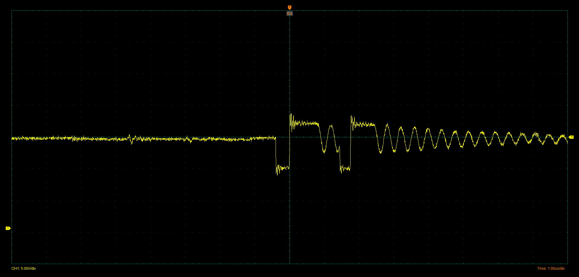
and @ No load VOut = 11.1V the SW output looks like this:

enter image description here

I'm not realy sure how to tune the COMP pin sins there is not alot of info in the datasheet about it(other than voltage setting no guide equations) but increasing C7 and decreasing R3 seem to make things a little better.

What could be wrong about the design? What exactly does that Compensation pin translates to? Could the values in the schematic be wrong?

\$\endgroup\$
15
  • \$\begingroup\$ Use a 10:1 probe without a gnd clip or tip using two resistor wire stubs to connect. Then use a small cap in feedback path to shunt R1 divider with RC = 200 ns going to Vfb. (2pf) avoid long lead lengths in feedback. Or scale down R1,R2 /10 and use 20 pF or so \$\endgroup\$
    – D.A.S.
    Commented Jun 6, 2021 at 11:45
  • \$\begingroup\$ A photo of your layout may help. \$\endgroup\$
    – Russell McMahon
    Commented Jun 6, 2021 at 11:57
  • \$\begingroup\$ @TonyStewartEE75 Excuse me but I was struggling to understand you, Do you mean to put a 2pF in parallel with R1? Russel McMahon updated the post with the pictures of my setup \$\endgroup\$
    – Pongo
    Commented Jun 6, 2021 at 13:22
  • \$\begingroup\$ Change R1, R2 to 850 ohms, 100 ohms as you have too much stray crosstalk, and add 10nH/cm to your schematic and get rid of that scope probe and use a proper one as I said. You’ll never get textbook waveforms with that layout. \$\endgroup\$
    – D.A.S.
    Commented Jun 6, 2021 at 14:44
  • \$\begingroup\$ Yes this reduces overshoot \$\endgroup\$
    – D.A.S.
    Commented Jun 6, 2021 at 17:56

1 Answer 1

1
\$\begingroup\$

This ringing is what you get from effective parasitic inductance (~1nH/mm) on long jumper wires without a star ground on chip and not using a ground plane. Ground leads are especially critical to lead inductance from switched caps. Thus then leads to excessive losses in the FET.

Your resonance may also be probe ground inductance.

\$\endgroup\$

Your Answer

By clicking “Post Your Answer”, you agree to our terms of service and acknowledge you have read our privacy policy.

Not the answer you're looking for? Browse other questions tagged or ask your own question.