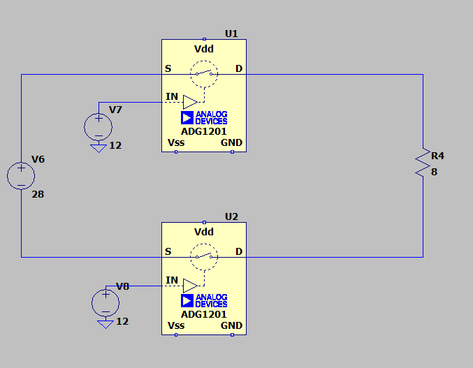
I am working with a safety related circuit that controls turning on/off load (solenoid of the hydraulic valve). I am wondering how I could implement this type of circuit using MOSFETs. Here is an equivalent circuit for the reference. Load voltage is 28 VDC. 2 control signals are 12V DC
-
2\$\begingroup\$ What safety standard are you designing to? I'm no expert, but what you propose provably won't satisfy IEC61508. \$\endgroup\$– Matt YoungCommented Jun 11, 2021 at 23:47
-
\$\begingroup\$ Are V7 and V8 separate signals, so that either switch can be on or off in any combination? \$\endgroup\$– AnalogKidCommented Jun 14, 2021 at 3:52
-
\$\begingroup\$ Correct. Control signals V7 and V8 can be on or off in any combination but only both control signals on will turn the load on. \$\endgroup\$– Alex DrakeCommented Jun 14, 2021 at 14:46
2 Answers
The ADG1201 is a signal switch device. It will not work as a power switch. Its internal resistance is around 120 ohms, 15 times greater than your load impedance.
Also, your drawing indicates a load current of 3.5 A, but the absolute maximum current allowed for this device is 30 mA.
To switch 3 A, you need a power transistor, either bipolar or MOSFET. If the control signal logic polarity is this:
+12 V = ON
0 V = OFF
then an n-channel power MOSFET or NPN power transistor will work as a low-side switch. Choose a part rated for at least 7 A and 60 V. Be sure to add a suppression diode across the solenoid coil.
Update:
To switch both sided os the coil, you will need three transistors. Two power transistors, one n-channel or NPN, and one p-channel or PNP. Plus one n-channel or NPN signal transistor to invert the signal for the high-side switch.
-
\$\begingroup\$ The ADG1201 is just for an example and it's not my intention to use. What I tried to show is that I need 2 switches to turn on/off positive side of the load and negative side of the load simultaneously. This is due to safety requirements. The questions is how to implement it using just power MOSFETs. Is there a way? \$\endgroup\$ Commented Jun 11, 2021 at 22:20
-
-
1\$\begingroup\$ Having a high and low side switch does not necessarily gain you the redundancy you want. Eg an overcurrent condition might cause both the mosfets to fail. Mosfets will usually fail short circuit. You might also want to detect that the solenoid circuit is intact and the resistance is within a valid range. If the mosfet were to fail, how would you detect it and how would you mitigate it? \$\endgroup\$– KartmanCommented Jun 12, 2021 at 3:33
-
\$\begingroup\$ Understood. I am not providing much information here about the redundancy requirements but it's not the part of my questions. My main questions is how to implement MOSFETs into a circuit per the diagram I provided. Is there a way? I would really appreciate if anyone could explain me if it is possible. \$\endgroup\$ Commented Jun 14, 2021 at 3:11
There exists "high side mosfet driver" like IR2117. Dual high & low side drivers like irs25607 or ucc27714 will suit for both mosfets.
Also, "solid state relay" can help too.

