3
\$\begingroup\$

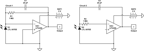
I have been trying to use an op-amp (LP324N) to amplify a LED that I am using as a photo sensor. The datasheet suggests that a single voltage supply is sufficient, but when Circuit 1 below is used I don't seem to be getting any output reading that changes with light exposure.

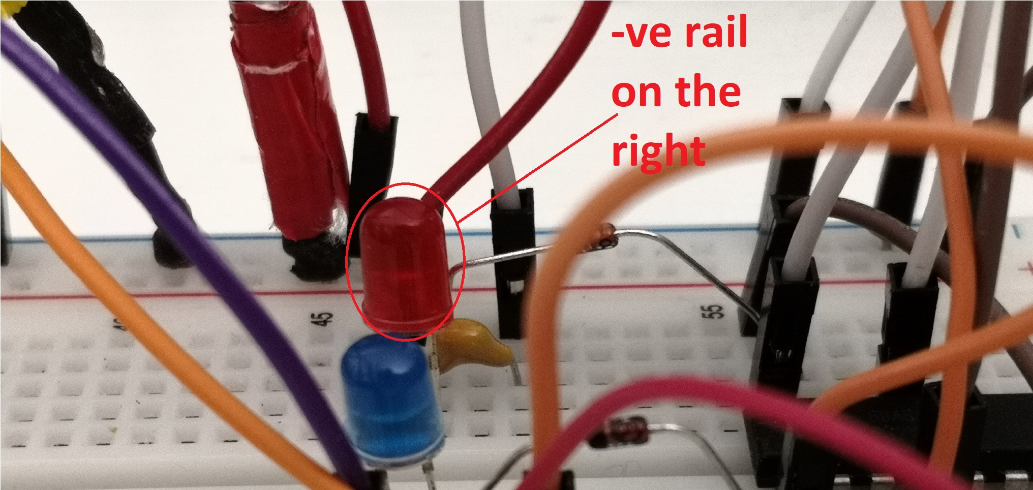
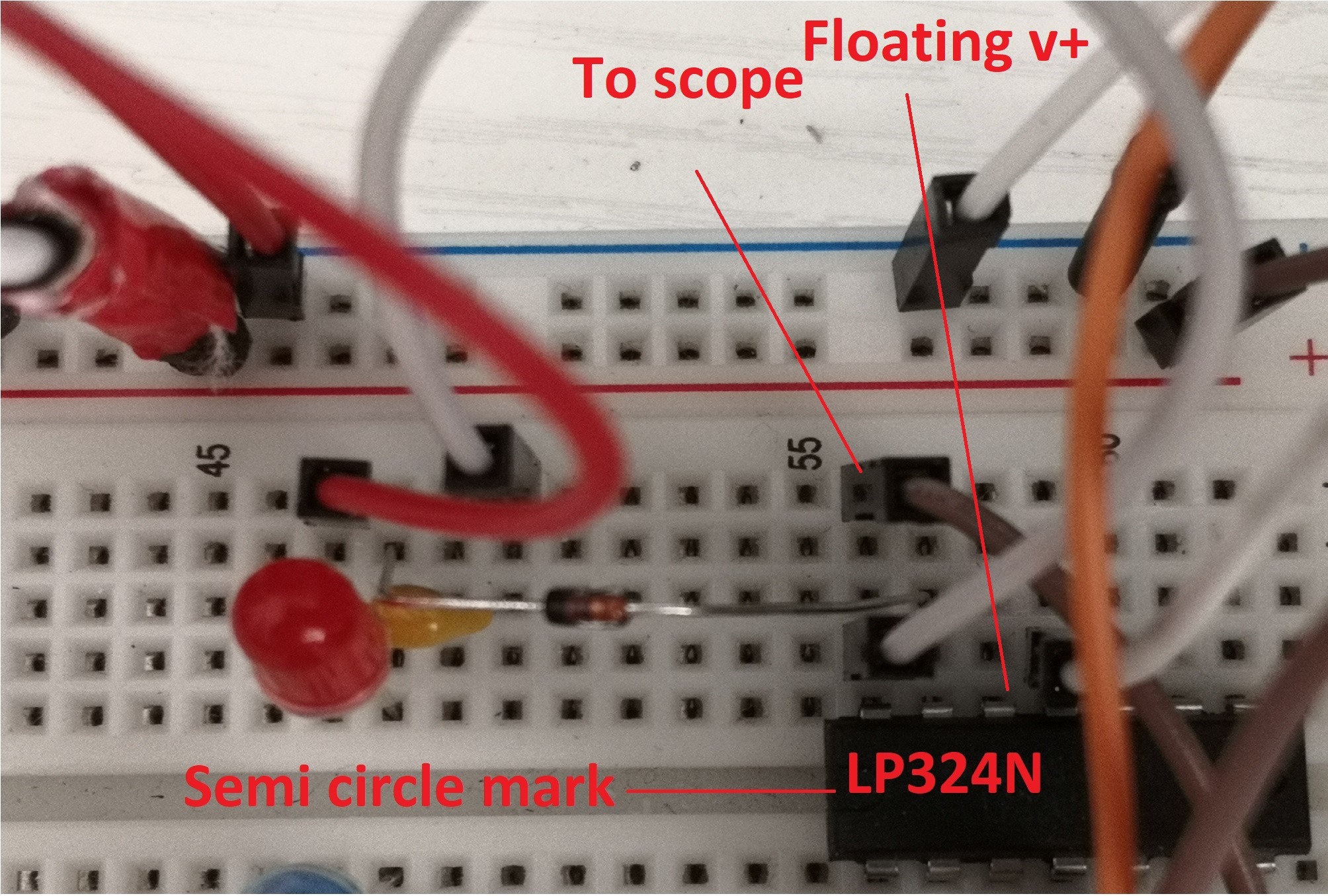
If instead I connect the resistance to the inverting input of the LM324N (cf. Circuit 2), and disconnect the non-inverting input that was previously grounded (so its floating now), I start being able to get output readings that vary with light exposure.

Can someone please help with:

  1. Understanding the logic of why this happens
  2. What am I doing wrong such that Circuit 1 doesn't work - from what I understand this should be similar to an inverting amplifier. Is this because R1 is not large enough with respect to the LED impedance?

Thanks.

schematic

simulate this circuit – Schematic created using CircuitLab

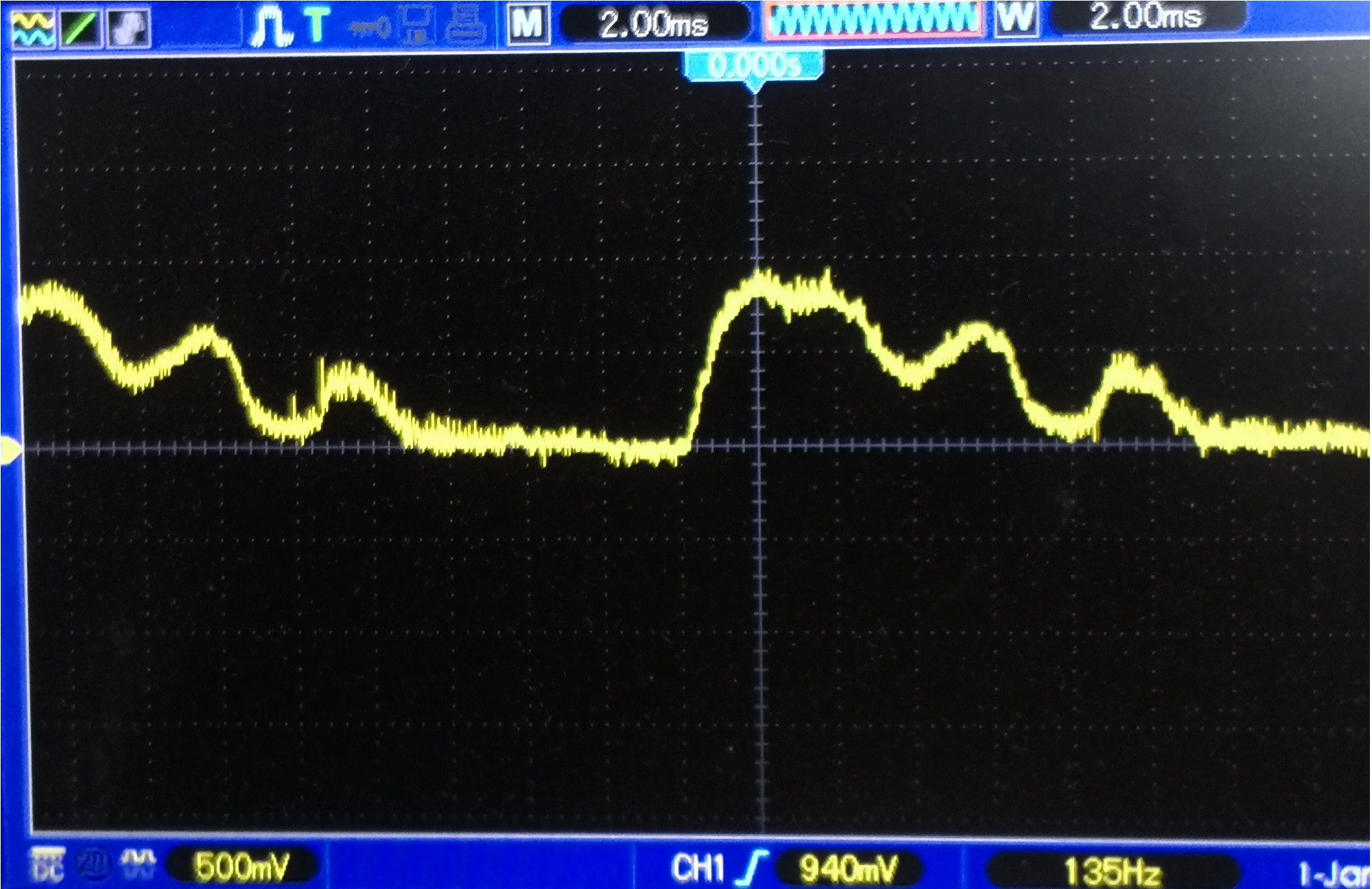
enter image description here enter image description here Changes with light intensity

\$\endgroup\$
5
  • 2
    \$\begingroup\$ Your 'scope trace shows a period of 20ms (50Hz). Are you sure that this is due to optical input? Quite possibly due to stray electric field as @JRE has suggested. \$\endgroup\$
    – glen_geek
    Commented Jun 13, 2021 at 13:14
  • \$\begingroup\$ The photodiode will drive IN- positive. On a unipolar supply, since the output cannot go -ve, the circuit cannot work. Revers the photodiode. \$\endgroup\$
    – user16324
    Commented Jun 13, 2021 at 13:54
  • 1
    \$\begingroup\$ The photodiode (LED) has the correct orientation as shown in your diagrams. When light is shone on the diode, the op amp's output must go positive. Conventional current flows from the amplifier's output down through the 1M resistor via the diode to ground and the op amp's inputs both remain at ground potential. To get a negative going output, reverse the orientation of the diode but for the circuit to operate like this it would need a negative voltage supply or to be biased up to mid-supply voltage. \$\endgroup\$
    – user173271
    Commented Jun 13, 2021 at 18:21
  • \$\begingroup\$ Why is everyone using LEDs instead of a proper photodiodes? LEDs are very bad photodiodes and the only possible reason for using them is having them readily available in the trash bin. \$\endgroup\$
    – fraxinus
    Commented Jun 14, 2021 at 11:18
  • 1
    \$\begingroup\$ For my purpose, because of cost and selectivity of wavelengths. I don't know about anyone else's reasons. \$\endgroup\$
    – Letshin
    Commented Jun 14, 2021 at 11:36

3 Answers 3

6
\$\begingroup\$

Let's take the second circuit first. What you are seeing is a pathological condition. Letting the +in float is asking for trouble, and you're getting it. Just as an exercise, try triggering the scope on the middle of the rising edge of your waveform. When you do this, you'll probably see the measured frequency change to 120 Hz. Whenever you see 120 Hz on a circuit which should be giving you DC, you know you're picking up AC hum, and I suggest that's what's happening. The floating input is varying at 120 Hz, which is 60 Hz rectified by internal diode junctions, and the output reflects that. Never, ever, ever let input pins float on an op amp. For that matter, I suggest you configure the 3 unused channels as followers and tie them to something convenient like 2.5 volts, which you make by using two resistors in series for +5 to ground.

Now, the first circuit. You're probably not aware of this, but LEDs are pretty bad photodiodes, and putting them in a colored body makes their response to "white" light even worse.

EDIT - Part of the reason that LEDs aren't great photodiodes is that their collecting area is very small. Dedicated photodiodes which are that small are usually intended to be used with high light levels, and can operate at higher frequencies. END EDIT

Also, running your op amps single-supply means that you can't measure what happens when a signal tries to go negative. I suspect that you've got issues with the offset voltage of your op amp, and your test illumination is insufficient to overcome it.

My first bit of advice is to get a second power supply, and drive your op amp with +/- 5 volts. If you're not willing to do that, try offsetting the input with a virtual ground.
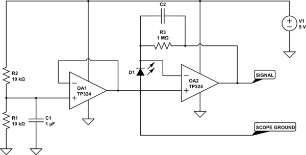
schematic

simulate this circuit – Schematic created using CircuitLab

A word of warning - You must use an isolated 5V supply. If you don't, when you connect your scope clip to the virtual ground, you may well get sparks, melted wire insulation, and dead components. Some cheap power supplies from places like China do not have isolated grounds. Caveat emptor applies.

If you're stuck on this, you can get around it by using an AC light source. Illuminate the LED with another LED tied face-to-face with a few turns of electrical or masking tape (not scotch or magic tape, since they are transparent.) Drive the new LED with a circuit like this
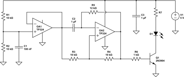
schematic

simulate this circuit

This will give a square wave at about 30 Hz, and you can use your scope's AC coupling to get rid of the 2.5 v offset on the photodiode output.
\$\endgroup\$
4
  • \$\begingroup\$ Thanks for this. I'm still trying to digest parts of what you've written. Can I ask in circuit 1, what the use of C1 is? Is it to stabilise possible fluctuations in the 2.5v from the divider? \$\endgroup\$
    – Letshin
    Commented Jun 14, 2021 at 14:15
  • 1
    \$\begingroup\$ @Zhao - Nope. It's to counteract the effect of the capacitance (typically 10s to 100s of picofarads) of the diode. Without some capacitance, the op amp will oscillate uncontrollably. For an LED, since it's very small you'd expect its capacitance to be small as well, so the feedback capacitor is also small. If you get this working, I suggest you try my LED source Idea, since this will give a very good square wave. Then vary the feedback capacitance and see how it changes the response of the amp. The rule is: the smaller the better, but not too small.... \$\endgroup\$ Commented Jun 14, 2021 at 17:16
  • 1
    \$\begingroup\$ Also notice - if you use the LED source idea, you can trigger your scope from the LED drive, and visually pick up the presence of very low photodiode outputs which would otherwise not reliably trigger your scope. Of course, if you do this you can fool yourself into seeing tiny effects which aren't really there - but that's on you. \$\endgroup\$ Commented Jun 14, 2021 at 17:21
  • 1
    \$\begingroup\$ And another tip. If you want to change the gain of of the op amp, due to greater or lesser illumination levels, you do so by changing the feedback resistor. When you do so, you can also change the feedback capacitor by about the same amount, and still have the op amp be stable. In fact, you MUST do it if you increase the resistor value. When you do that, you will slow down the overall response, so at higher gains you'll be restricted to lower frequencies. Probably not an issue, but I thought I'd mention it. \$\endgroup\$ Commented Jun 14, 2021 at 17:25
4
\$\begingroup\$

324 inputs are weak current sources, if you don't connect them to anything they will rise to near the positive supply voltage

in circuit 2 both inputs float high but the inverting input is pulled down by the LED/photodiode resulting in a positive imbalance and thus a positive output signal.

\$\endgroup\$
3
\$\begingroup\$

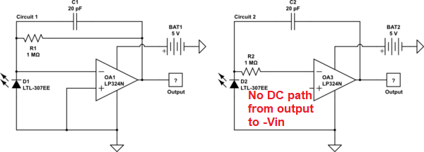
The 2nd circuit doesn't work because there is no DC negative feedback and the op-amp output just slings itself against the power 0 volt rail trying to make the inverting input voltage equal 0 volts. It cannot do this because there is no DC path from output to that pin.

enter image description here

\$\endgroup\$
10
  • \$\begingroup\$ The second circuit works actually - are you referring to the first circuit? \$\endgroup\$
    – Letshin
    Commented Jun 13, 2021 at 10:19
  • 5
    \$\begingroup\$ @Zhao: That a circuit does something doesn't mean that it is working properly. When you leave the "+" input floating (disconnected,) it takes on a value that is determined in part by the internal circuit of the IC and in part by influences from other electric fields close by. In your case, it floats to a value that is close enough to correct for your circuit to work. If anything around your circuit changes, then the circuit will stop working or not work as well. That is not a circuit you should rely on. \$\endgroup\$
    – JRE
    Commented Jun 13, 2021 at 11:55
  • 1
    \$\begingroup\$ The left circuit should work well if you use a photodiode (anode to ground) instead of an LED. The right circuit is not worth discussing. \$\endgroup\$
    – user173271
    Commented Jun 13, 2021 at 11:56
  • 2
    \$\begingroup\$ You simply cannot build op-amp circuits which leave an input floating and call them working, period. You're not meeting the "interface contract" of the part, to use a software term. \$\endgroup\$
    – Kaz
    Commented Jun 13, 2021 at 20:48
  • 2
    \$\begingroup\$ If you use a part with multiple op-amp units on the same IC, and do not use all the op-amps, you must not even leave the unused op-amps floating. Never mind the inputs of the used part! \$\endgroup\$
    – Kaz
    Commented Jun 13, 2021 at 20:49

Your Answer

By clicking “Post Your Answer”, you agree to our terms of service and acknowledge you have read our privacy policy.

Not the answer you're looking for? Browse other questions tagged or ask your own question.