9
\$\begingroup\$

This question seeks a definitive and precise answer to a question regarding the transient response of a transmission line.

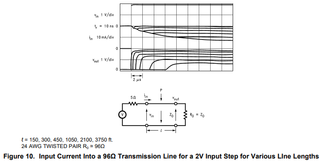
Figure 10 of TI Application Note snla026a contains a graph showing (among other things) the current into transmission lines of various lengths driven by step voltages.

enter image description here

The discussion in the text of the application note gives a qualitative account of the current into the transmission line, but does not provide a formula for the current waveform. Furthermore, the graph is somewhat confusing.

[It appears to me that the following is what is illustrated in the graph. Initially, the applied 2V sees an impedance consisting of the 5\$\Omega\$ discrete resistor plus the 96\$\Omega\$ nominal characteristic impedance of the line, and jumps to approximately 20 mA. The current then falls, but the the formula for this fall is not clear. At approximately the time when the voltage signal arrives at the far end of the transmission line, the current stops it fall, and remains more or less stable (at least for the remainder of the time spanned by the graph.)]

Suppose one has a transmission line, long enough to be considered "infinite" for our purposes. Suppose the the driven end of the transmission line has a termination resistor thus:

schematic

simulate this circuit – Schematic created using CircuitLab

Assume the transmission line is "lossy" in the sense that there is some non-zero resistance per unit length of the wire.

Assume that the switch is initially open, and the transmission line is quiescent -- there is neither voltage nor current anywhere in the line.

When the switch is closed, what will be the voltage and current waveforms at the driven end of the transmission line? Particularly, what predictions about the waveforms can be made from The Telegrapher's (Heaviside's) Equations:

$$V_x = -LI_t - RI$$ $$I_x = -CV_t - GV$$

Whatever the waveforms may be, will it be the case that the instantaneous voltage is always equal to the instantaneous current times a constant?

[Based upon the TI application note, and the fact that the impedance of a transmission line varies with frequency, I do not believe that the instantaneous voltage is always equal to the instantaneous current multiplied by a constant. However, I have seen enough instances where the current into a transmission line prior to any reflections is the voltage divided by the characteristic impedance the question of whether that is in fact the case to be a point that may be in dispute.]

To some approximation, the voltage and current waveforms will have step-function behavior, with the ratio between voltage and current equal to the characteristic impedance \$Z_0\$ of the transmission line. That is, to some approximation, the transmission line will appear to be a pure resistance to the driving circuit. We also know that no experimental technique will ever demonstrate an exact step function. So, I am specifically asking whether the driving circuit will see the transmission line as a pure resistance according The Telegrapher's Equations, or whether those equations predict the driving circuit will see a more complex load. That is, I want an answer based on the mathematical model of the Telegrapher's Equations, and not simply an approximation which is sufficiently imprecise that the instantaneous voltage is equal to the instantaneous current times a constant. (Unless that is what in fact is predicted by the Telegrapher's Equations).

For reference, the impedance of a lossy transmission line is frequency dependent, and is given by:

$$Z=\sqrt{\frac{R+j\omega L}{G +j\omega C}}$$

If the transmission line is lossless, i.e. R=G=0, then

$$Z =\sqrt{\frac{L}{C}}$$

and the impedance is frequency independent.

Also, if \$\frac{R}{L} = \frac{G}{C}\$ the characteristic impedance will in that case also be frequency independent.

Edit: Although I do not presently have a formula for the transient response, if I have done my math correctly, the steady state current response resulting from closing the switch, (if R1 is 0), according to the Telegrapher's equations can be calculated thus:

In steady state the system variables do not change with time, so \$I_t = 0\$ and \$V_t = 0\$. So:

$$V_{x(steady)} = -RI_{steady}$$ $$I_{x(steady)} = -GV_{steady}$$

Therefore

$$V_{xx(steady)} = -RI_{x(steady)} = RGV_{steady}$$

Therefore

$$V_{steady} = k_1e^{\sqrt{RG}x} + k_2e^{-\sqrt{RG}x}$$

Since the voltage at the origin is determined by the applied step, and the voltage at infinity must be 0,

$$V_{steady} = V_0e^{-\sqrt{RG}x}$$

And

$$V_{x(steady)} = -\sqrt{RG}V_0e^{-\sqrt{RG}x}$$

$$I_{steady} = -\frac{1}{R}V_{x(steady)} = \sqrt{\frac{G}{R}}V_0e^{-\sqrt{RG}x}$$

At the origin, (assuming my math is correct)

$$I_{0(steady)} = \sqrt{\frac{G}{R}}V_0$$

This result implies that the apparent "impedance" at steady state (i.e. the input voltage divided by the input current) is NOT the not the nominal (i.e. high frequency) characteristic impedance of \$\sqrt{\frac{L}{C}}\$, but \$\sqrt{\frac{R}{G}}\$.

If my math is correct, any correct solution to the transient problem must give the steady state current as

$$I_{0(steady)} = \sqrt{\frac{G}{R}}V_0$$

and any solution that gives \$I_{0(steady)}=\sqrt{\frac{C}{L}}V_0\$ (except when \$\frac{G}{R} = \frac{C}{L}\$) must be incorrect.

\$\endgroup\$
7
  • \$\begingroup\$ " switch is initially open, and the transmission line is quiescent -- there is neither voltage nor current anywhere in the line. When the switch is closed, what will be the voltage and current waveforms at the driven end of the transmission line? " It's a double throw switch .... \$\endgroup\$
    – D.A.S.
    Commented Jun 24, 2021 at 20:05
  • \$\begingroup\$ Good catch. Originally had a single throw. Reverting. \$\endgroup\$ Commented Jun 24, 2021 at 20:07
  • \$\begingroup\$ if you expect a canonical answer then you ought to cite a reference to your assumptions on the Heaviside equations which are normally in derivative form {x,t} \$\endgroup\$
    – D.A.S.
    Commented Jun 24, 2021 at 20:47
  • \$\begingroup\$ @TonyStewartEE75 the equations are in partial derivative form. Perhaps you are not familiar with subscript notation for partial derivatives. \$\endgroup\$ Commented Jun 24, 2021 at 20:52
  • \$\begingroup\$ Ok well at t=0 the source sees \$R+\sqrt{L/C}=Z_O\$ as the initial load. So Zo is equivalent to an R until the reflected wave returns with twice the voltage or almost in the lossy case. \$\endgroup\$
    – D.A.S.
    Commented Jun 24, 2021 at 21:09

4 Answers 4

7
\$\begingroup\$

I am specifically asking whether the driving circuit will see the transmission line as a pure resistance according The Telegrapher's Equations, or whether those equations predict the driving circuit will see a more complex load.

The source will see R1+Z and Z varies with time if it is lossy. So a lossy tranmission line will look like a complex load. I suppose you could take the Fourier transform of Z and find out what the load looks like over time. (my intuition tells me that it will approach the characteristic impedance but never get there until infinity at t=inf jw=0 its not really DC until t=inf!)

$$Z=\sqrt{\frac{R+j\omega L}{G +j\omega C}}= \text{Changes with frequency and time} $$

If the transmission line is lossless , then by the equation there is no time dependence and the load looks like a resistor per the equation.

$$Z =\sqrt{\frac{L}{C}}=\text{Constant}$$

\$\endgroup\$
6
\$\begingroup\$

I am specifically asking whether the driving circuit will see the transmission line as a pure resistance according The Telegrapher's Equations, or whether those equations predict the driving circuit will see a more complex load.

The telegrapher's equations do not indicate that the impedance seen by the source is a pure resistance. They only indicate that the impedance is: -

$$\sqrt{\dfrac{R + j\omega L}{G + j\omega C}}$$

So then you can mess with R, L, G and C and get some more complexity but, if you are prepared to put up with some losses you can make the ratio of R:L the same as G:C and you get what is known as a distortionless line (also defined as the Heaviside condition).

And, for this case, the input impedance is constant irrespective of frequency. It's also purely resistive.

Clearly, for a non-distortionless t-line, at quite high frequencies the impedance is \$\sqrt{\frac{L}{C}}\$ and this is also a resistive input impedance.

For audio (on a fairly loss-less line) it cannot behave distortionlessly because G is normally very, very small and R usually is much greater than \$j\omega L\$ (at audio) hence, the impedance tends to become this: -

$$\sqrt{\dfrac{R}{j\omega C}}$$

At DC, the impedance has to become this: -

$$\sqrt{\dfrac{R}{G}}$$

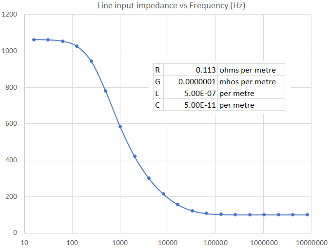
So, you can see that a fairly low loss infinite line will have an input impedance like this: -

enter image description here

This impedance magnitude graph was made in Microsoft excel using the four variables shown (approximately what a telephone cable would be). Note that at around 1 kHz, the impedance is about 600 Ω. This is important in regular telephony and is the "standard" impedance used for audio transmission.

Impedance formula magnitude (not too hard to prove): -

$$|Z_0| = \sqrt{\sqrt{\dfrac{R^2+\omega^2 L^2}{G^2+\omega^2 C^2}}}$$

Impedance formula angle (a tad harder to prove): -

$$\text{Angle} = \dfrac{\arctan\left[{\dfrac{\omega\cdot (LG-CR)}{RG+\omega^2 LC}}\right]}{2}$$

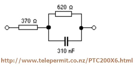
The 600 Ω point mentioned and shown above will be "complex" (not 100% resistive) hence, for telephone anti-side-tone circuits they tend to balance using this impedance: -

enter image description here

This circuit is a decent representation of a typical telephone cable across the lower audio bandwidth.

When the switch is closed, what will be the voltage and current waveforms at the driven end of the transmission line?

Once you have decided what the t-line input impedance is (it equals the characteristic impedance for an infinite line over all time) then it's simple impedance divider maths using R1 and Zin.

When the switch is closed, what will be the voltage and current waveforms at the driven end of the transmission line?

Only when the line is distortionless or the frequency is high enough to disregard R and G.

Also for reference, the impedance of a lossy transmission line is frequency dependent

It's usually frequency dependent but not so for a distortionless line.

\$\endgroup\$
1
  • \$\begingroup\$ I think it is a very educational answer.. Deriving the frequency dependence of transmission line impedance was on my infinite mental to do list for years and now I can check it off 😊 \$\endgroup\$
    – tobalt
    Commented Jun 7, 2022 at 17:52
2
+200
\$\begingroup\$

This is an interesting problem.

What you are asking for is the inverse Laplace transform of

\$I(s) = \frac{V_0}{s}\sqrt{\frac{G+sC}{R+sL}}\$

which will give you the exact solution you seek but which doesn't have a closed form solution.

We can get some information from it:

The initial value theorem lets us work out the initial value of the current:

\$I(0+) = \lim_{s \to \infty} s\frac{V_0}{s}\sqrt{\frac{G+sC}{R+sL}} = V_0\sqrt{\frac{C}{L}} \$

so the current starts at the lossless surge impedance value.

The final value theorem gives the limit as \$t \to \infty \$ of \$I(t)\$ as \$V_0\sqrt{G/R}\$, which you derived.

Using properties of the Laplace transform:

if \$\mathcal{L}\{f(t)\}=F(s)\$ then \$\mathcal{L}\{f'(t)\}=sF(s)-f(0)\$

you can deduce the transform of the derivative:

\$\mathcal{L}\{I'(t)\}=V_0\sqrt{\frac{G+sC}{R+sL}}-V_0\sqrt{\frac{C}{L}}\$

and using the initial value theorem again, you can show that

\$I'(0+) = \lim_{s \to \infty} s(V_0\sqrt{\frac{G+sC}{R+sL}}-V_0\sqrt{\frac{C}{L}}) = V_0\sqrt{\frac{C}{L}} (\frac{G}{2C}-\frac{R}{2L})\$

So the leakage conductance G tends to increase the current with time, and the series resistance R decreases it. You can understand this from considering the propagation of the forward travelling wave, in time t it travels \$\frac{t}{\sqrt{LC}}\$ which causes a leakage current through G of \$\frac{V_0 tG}{\sqrt{LC}}\$, only half of which has had time to get back to influence the input current, so the increase in current is \$\frac{V_0 tG}{2\sqrt{LC}}\$ in accordance with the derivative above.

In a similar fashion, the series resistance R drops the current as the wavefront voltage drops as the wave travels along the line.

The transition from the initial value to the final value is smooth, similar to an exponential decay, and it is possible to estimate the time constant as follows:

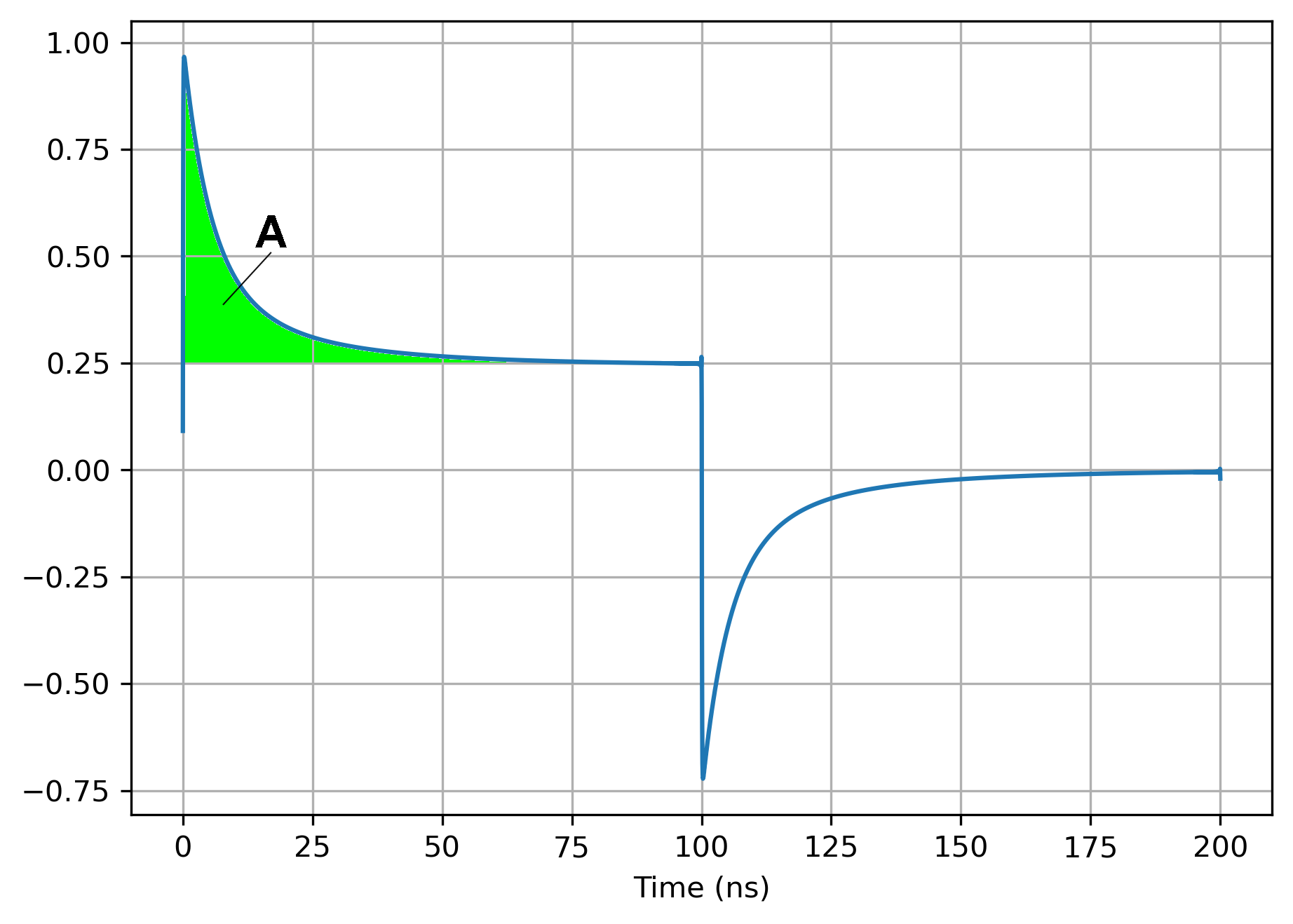
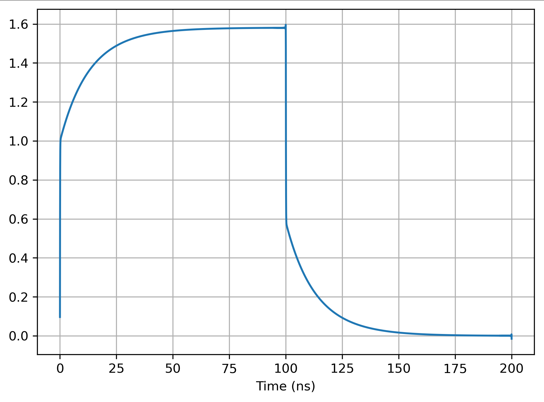
Here is a simulation of the current into a 50 ohm line, velocity factor = 1, with R=42, G=0.001 with 50V step (so initially 1A into \$\sqrt{\frac{L}{C}}=50\Omega\$, settling to \$50\sqrt{\frac{G}{R}} = 0.244A\$:

enter image description here

The voltage returns to 0 at 100ns. Although there is no closed form of the waveform, you can calculate the area A between the waveform and the final value using properties of the Laplace transform.

If this was an exponential decay \$I = I_0 + I_1 e^{-t/\tau}\$ then \$A = I_1 \tau\$. So we can estimate an effective time constant \$\tau_e = A/I_1\$ which will turn out to have a particularly simple form.

Denoting \$\tau_R = L/R\$ and \$\tau_G = C/G\$ then

\$\tau_e = \frac{1}{2}(\tau_R + \sqrt{\tau_R \tau_G})\$

In the above waveform, \$\tau_R = 4ns\$ \$\tau_G = 67ns\$ and \$\tau_e = 20ns\$ which is probably good enough to allow you to sketch the waveform. The waveform is not exponential decay so I am not claiming that this is accurate, but that this is a way to estimate the wave shape and the time over which it varies.

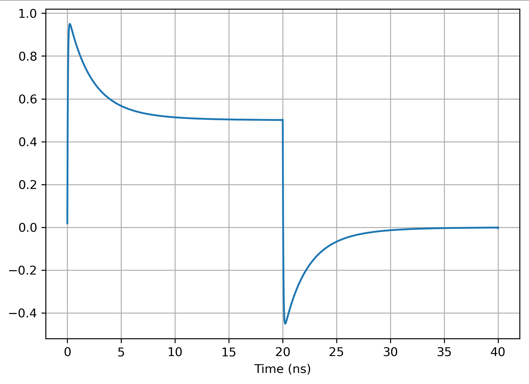
Another example: enter image description here

R = 100, G = 0.01, \$\tau_R = 1.7ns\$ \$\tau_G = 6.7ns\$ and \$\tau_e = 5ns\$

Another:

enter image description here

R = 10, G = 0.01, \$\tau_R = 16.7ns\$ \$\tau_G = 6.7ns\$ and \$\tau_e = 27.2ns\$

The way I simulated the transient response was using a time harmonic solution. The frequency dependence of the characteristic impedance seen at the input of a long cable is well known.

\$Z_0(\omega) = \sqrt{\frac{R+j\omega L}{G+j\omega C}} \$

So if you drive the cable from a sinusoidal source, you can compute the magnitude and phase of the current from \$Z_0(\omega)\$. If you drive the cable with a square wave, you can decompose that into harmonics and calculate the amplitude and phase of the current of each, then sum them to get the total current. This is all I did for the simulations above. Well I did one more thing - I made sure I oversampled considerably and used a low-pass filter to minimise the Gibbs phenomenon at the transitions - just tidied up the plots. This is a bit crude and could be improved.

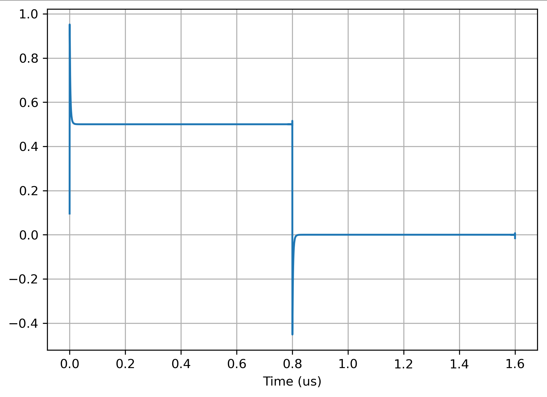
Of course, to approximate the step response you have to be careful that the effect of the previous pulse has dissipated before the next one. This is relatively easy as this is a lossy line - it doesn't tend to store the charge so it is usually a matter of waiting enough time constants for the charge to dissipate. The plots I showed I had the edges close together to show the transient detail, you would typically increase the periods to get a better approximation of the step, like:

enter image description here

this is only 32k points, and the current is more than 60dB down at the next rising edge, if that is not enough, wait a few extra time constants. Of course, this is dependent on the various time constants involved. It is self-checking as it computes the residual current. I would think that this could be made to be sufficiently accurate for any engineering problem I can envisage. I'd be interested to know of the applications where it may fail.

Alternatively you could look at simulating the pulse response in the Fourier domain. You can't get the step response as it has infinite energy, but a pulse you can. It is just a matter of the type of quadrature you use on the Fourier integral. Using the square wave approximation is equivalent to simply sampling in the frequency domain, you may do better trying to invert the Fourier transform. Alternatively, there is an extensive literature on numerically inverting Laplace transforms, and that could also be a good place to look.

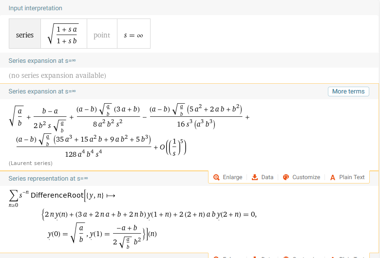
You mentioned in a comment that you were considering constructing a power series solution from the Laplace theorems on derivatives and initial values. This seems like hard work, it is likely much easier to directly work from the Laurent series for the impedance:

\$\sqrt{\frac{G+sC}{R+sL}}\$

from alpha:

enter image description here

this directly allows you to express

\$\frac{1}{s}\sqrt{\frac{G+sC}{R+sL}} = \sum \frac{a_n}{s^n}\$

and gives you a recurrence relationship for the coefficients \$a_n\$. You can then invert this term by term to get the taylor series for the step response.

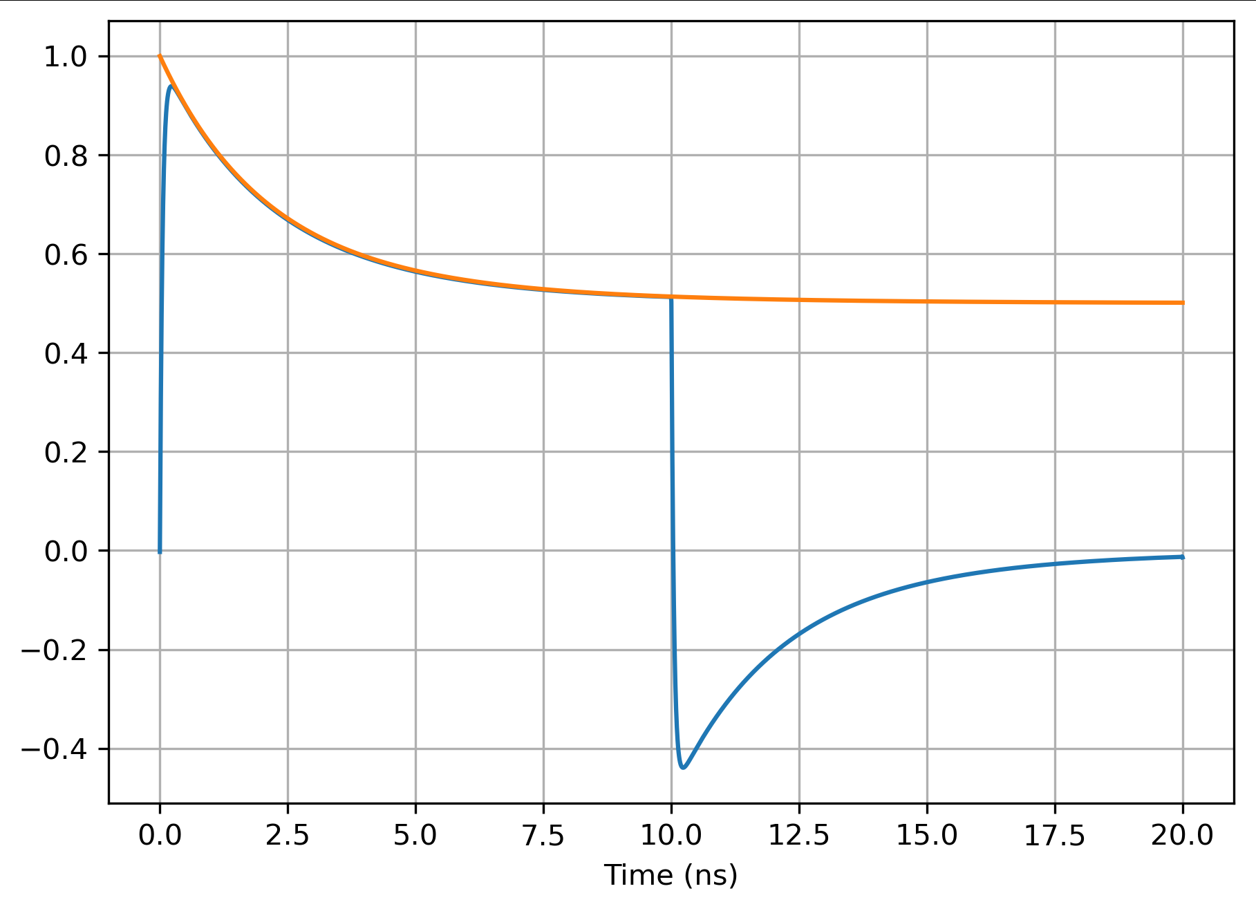
This works - I did a very quick mash up. You have to be careful with scaling, but here is a typical plot:

enter image description here

R = 100, G = 0.01, 50 ohm line, vf = 1, 100 terms in the series, coefficients calculated according to the recurrence on the alpha site here.

I suspect that most of the discrepancy around the impulse is not the state of the line but the filtering I used to reduce the Gibbs. I'm sure that this could have be improved, and after all, no-one has a perfect step to hit the line with.

I'm intrigued if you have an application for this or is it an academic exercise? In the problems I have encountered this is all a bit moot as \$R\$ is not constant but tends to be proportional to \$\sqrt{f}\$ due to the skin effect and this tends to give a \$\frac{1}{\sqrt{t}}\$ term in the step response.

Thanks for the interesting problem!

\$\endgroup\$
5
  • \$\begingroup\$ The question is mostly curiousity, but I became interested in it while trying to find a good termination for a transmission line operating at a frequency well below where characteristic impedance plateau's at \$\sqrt{\frac{L}{C}}\$. I kept seeing claims that current is \$V\sqrt{\frac{C}{L}}\$ until reflection, which I "knew" was wrong. \$\endgroup\$ Commented Jun 8, 2022 at 1:11
  • \$\begingroup\$ Do you know of a numerical technique to find successive approximations to the inverse Laplace transform mentioned in your answer? \$\endgroup\$ Commented Jun 8, 2022 at 1:13
  • \$\begingroup\$ I don't know much about approximating Laplace inversions, what I was saying is that you can compute the current into the infinite line if you excite it with a sine wave using the well known impedance formula. So if you excite it with a square wave you can simply sum the currents from each harmonic to get the total current. \$\endgroup\$
    – Tesla23
    Commented Jun 8, 2022 at 1:42
  • \$\begingroup\$ I appreciate the work you have done on this problem, but I have doubts that a square wave response will correctly model a step response. At the rising edge of a square wave, the t-line is not necessarily in it's quiescent state, as it would be before the rising edge of a step input. Rather, the t-line is in some state left which is residual from the previous excitations. \$\endgroup\$ Commented Jun 11, 2022 at 10:41
  • \$\begingroup\$ Your calculation of the first derivative of the current gives me an idea for solution -- constructing a Taylor series by finding all the derivatives of the current --at zero if that converges, or at some later point if necessary for convergence. (Also, I agree that there is no closed form solution constructed solely from the common trig and exponential functions, I am not entirely convinced there is no closed form solution involving more exotic functions such as, for example, the modified Bessel function of the first kind.) \$\endgroup\$ Commented Jun 11, 2022 at 10:52
0
\$\begingroup\$

I am too "old" (and "lazy" :-) ...) to make a complete "mathematical calculation" of this effect.
Generally, we consider "frequency" effects and use the "frequency" tools for calculating whatever is needed, because generators apply repetitive waves.

But sometimes, we should also use the "time" tools for some systems, because the characteristics change with "time" and not only with "frequencies".

From this paper, I can only list the effects of the "skin" effect when a step pulse is applied.
I should add also this paper.

We can say, based on an analogy with AC skin effect theory:
• Increased circuit resistance (within a transient period) and increased joule heating is likely
• The conductor inductance is modified (within a transient period)
• A transient voltage associated with this transient impedance is also likely leading to discrepancies in the assumed dynamic response of a given circuit (unexpected and increased damping).
Thus, it is immediately clear that certain situations will experience the transient skin effect
• Some switched-mode power electronic circuits
• Both DC and AC power system transients
• Pulsed DC applications

I just remember, at one lab, that when you apply only one power step pulse on a cylindrical bar, one should not touch the "bar" because it can be hot on the superficial part, but it can be cold inside, then after heat spread inside ...

\$\endgroup\$

Your Answer

By clicking “Post Your Answer”, you agree to our terms of service and acknowledge you have read our privacy policy.

Not the answer you're looking for? Browse other questions tagged or ask your own question.