0
\$\begingroup\$

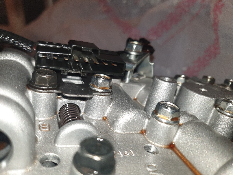
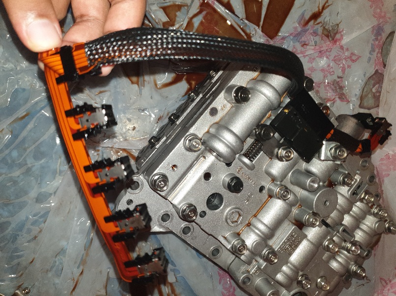
I have extracted this wiring harness from the valve body of the transmission. But when I did a continuity test with a multimeter to diagnose if there was any problem with the wires, there was no buzzing sound when I connected the pins in this image :

pins

To the other end of the wiring harness as in this image:

enter image description here

I have also recorded a video and uploaded it on YouTube to show what I did in this link :

https://youtu.be/bQJ5TIurny8

My question is, how can I test for continuity in those types of ribbon wires?

\$\endgroup\$
5
  • \$\begingroup\$ Is there supposed to be continuity between the pins you're testing? What does the ohmmeter read? \$\endgroup\$
    – nanofarad
    Commented Jul 7, 2021 at 22:52
  • \$\begingroup\$ @nanofarad Yes they should have continuity, because those pins will be plugged into the solenoid and those solenoid will get instructions from TCM (transmission control module) through those wires to make them function. The ohmmeter doesn't show anything either \$\endgroup\$
    – John Sall
    Commented Jul 7, 2021 at 23:10
  • 2
    \$\begingroup\$ By "doesn't show anything", you mean actively showing an open-circuit indication, right? There's not much to go off here information-wise, unfortunately. \$\endgroup\$
    – nanofarad
    Commented Jul 7, 2021 at 23:22
  • \$\begingroup\$ sounds like you have a bad cable \$\endgroup\$
    – jsotola
    Commented Jul 8, 2021 at 0:06
  • \$\begingroup\$ If your multimeter isn't beeping, it doesn't mean that the continuity test isn't working. In means that there is no continuity between the two points that you are testing, i.e, there is a break in the connection somewhere. \$\endgroup\$ Commented Jul 8, 2021 at 5:02

0

Your Answer

By clicking “Post Your Answer”, you agree to our terms of service and acknowledge you have read our privacy policy.

Browse other questions tagged or ask your own question.