I am trying to discretize the transfer function of my compensation.
After modelling my system in continuous domain thanks to books of Christophe Basso and books of Erickson Robert W., Maksimovic Dragan, I did the compensation of my system in the continuous domain but by knowing that I will discretize this compensation. So I needed to take into account the effect of sampling and of the ZOH in the continous domain for doing the right compensation (as some of the members of this forum help me to do it). Then I used the "tustin" method for discretizing the transfer function of my compensation.
In order to be sure of my results, I decided to use Simulink to verify that the 2 systems, the one in the continuous domain and the one mixed between continous and discrete, give the same response. Here is my problem they do not give the same response.
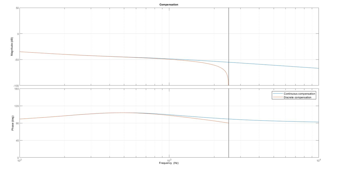
Here is the transfer function of my compensator in the discret and continuous domain for a phase margin equal to 70°
Here are what I wanted to simulate on Simulink.
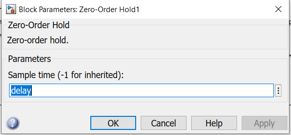
The first picture is in the continuous domain with the Zero Order Hold block given by Matlab where we can set the "sample time" to the value we want. I set it to 200 µs as my sampling frequency is 5kHz
The second picture is in the continuous domain with the transfer function of a Zero Order Hold find on wikipedia with "T" set to 200µs :
And when I look the response between the both circuit where only the ZOH block is different, the responses of the different diagramm are differents. This is a point that I do not understand. And I would say that the correct simulation is the one with the transfer function of the ZOH from wikipedia as regards of the response and the effect of the phase margin on the response.
The third picture is the mixed diagramm :

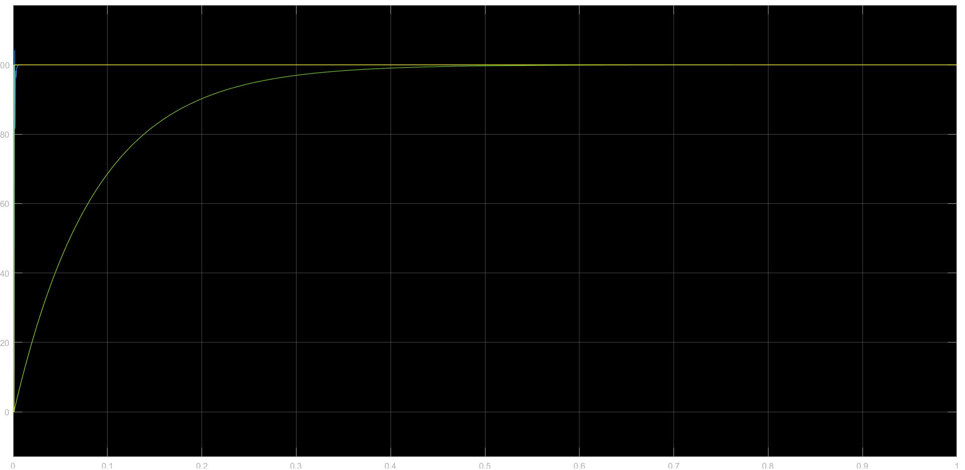
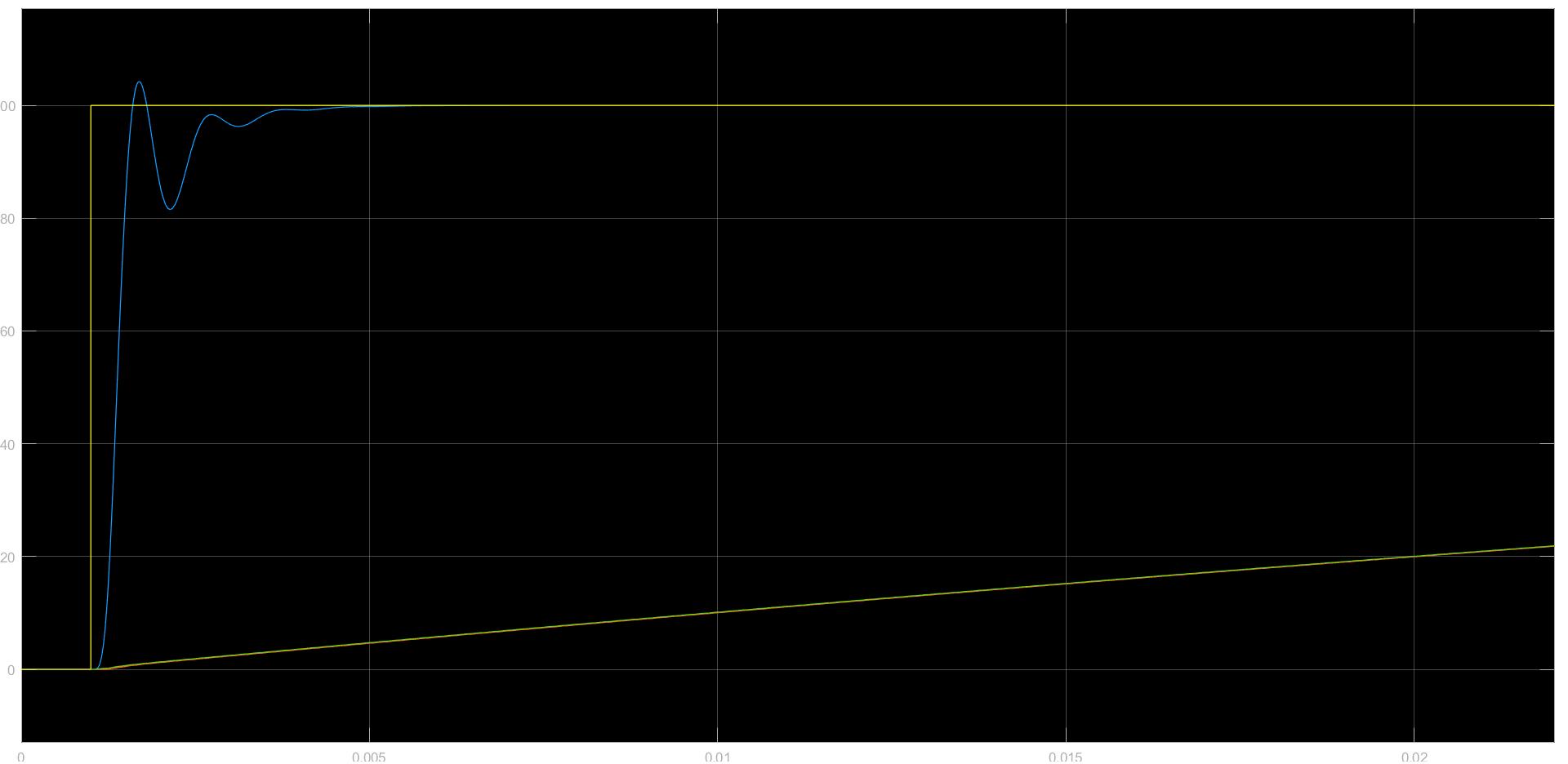
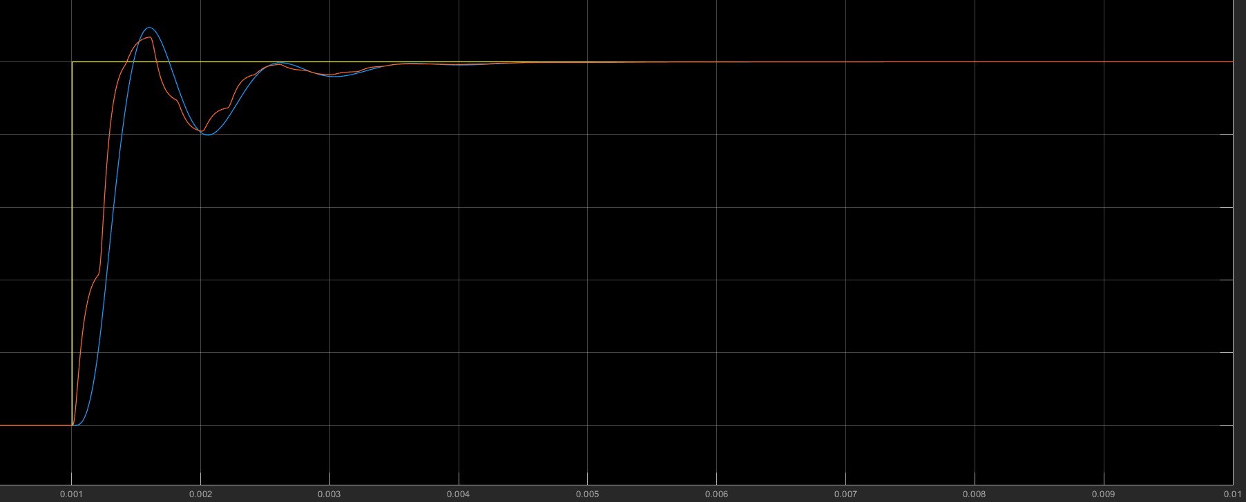
Finally here are the responses :
where the green response whose the settling time and rise are the longest corresponds to the 1st picture and the third picture. They completely fit, so it is not possible to see 2 curves. And the blue reponse corresponds to the 2nd picture (the one with the ZOH transfer function from wikipedia which according to me seems to be the right... )
According to me all the diagramms that I showed you are the same, or actually I set it to be the same ... Could you, please, tell my why the systems are different ?
Tell me if you need more informations.
Thank you very much and have a nice day :)
----------------------------------E D I T-----------------------------------
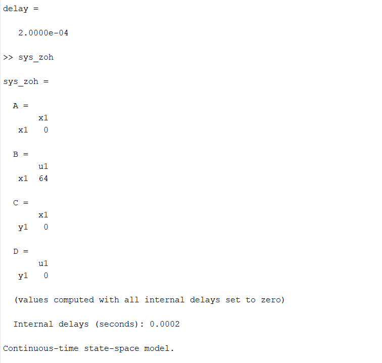
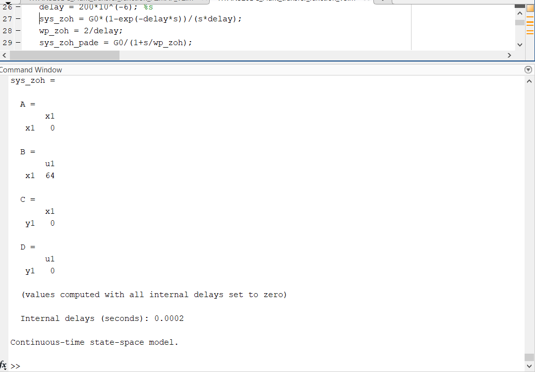
The parameter control box is an LTI Block and its parameter is the transfer function *sys_zoh" whose the definition is the following :
I added the ZOH block :
I am sorry for the late response, I do not have matlab at home ...
---------------------- DOUBLE EDIT ----------------------------------------
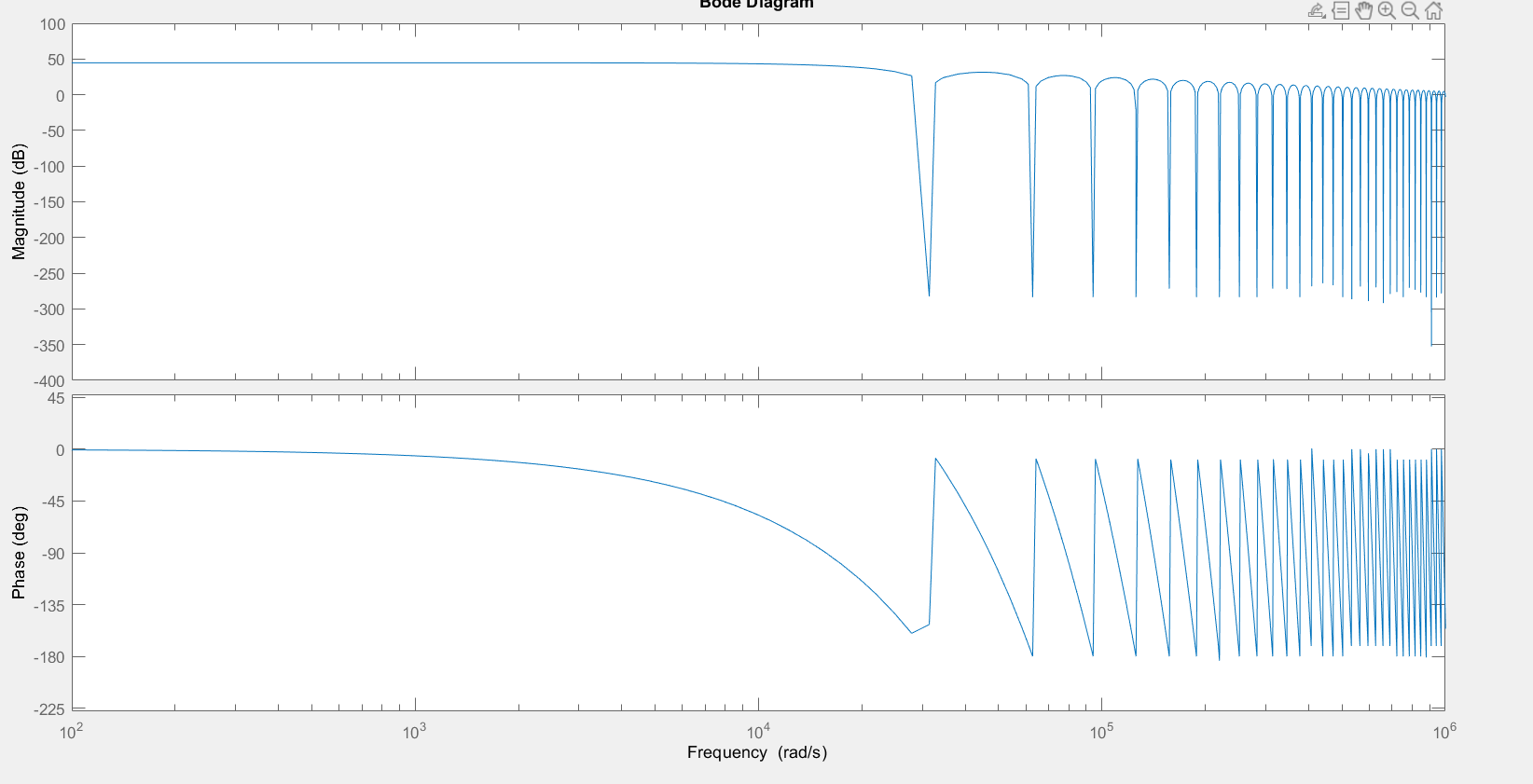
Here is how I define the sys_zoh transfer function and its bode plot
Thank you :)

