Dear people of the internet, I seek your wisdom in figuring out a specific (analog) situation that puzzles me.
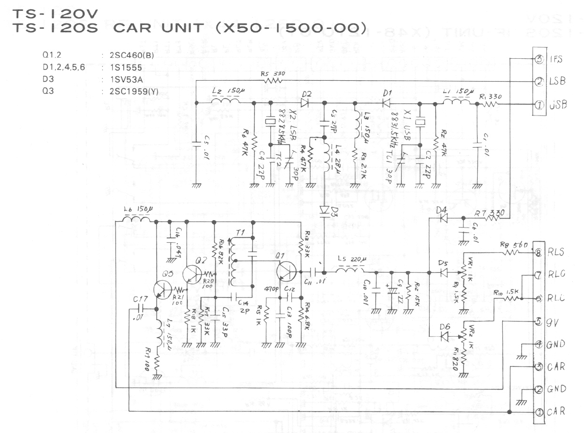
Recently I got my hands on a HF transceiver, the Kenwood TS-120V, which was not working. Upon investigation, it turned out to be a very common (so say the internet) problem with a PLL unlock, due to a missing carrier tone. This is the carrier schematic of the unit:
As many have previously said regarding this issue, I immediately started suspecting Q1 to be the issue. After taking it out of circuit, my suspicions were proved correct by the help of those cheap component testers - the gain (hFE) of the removed Q1 (2SC460B) measured to be 26. This is way below the rated 60 to 120 values for hFE for the B group of transistors.
I read somewhere that a suitable replacement for the 2SC460 (which is long gone from production) is the 2SC945 (which is somewhat available in local shops, but still long gone from production). I immediately ordered couple of 2SC945P (P grade that have a hFE range of 200-400) from a local shop. The received 2SC945P's all had a current gain (tested with the same component tester, unfortunately only at one operating point) of a bit over 300. Putting one 2SC945P in the place of Q1, I was not able to get the oscillator up and running. Note: I have removed the carrier board out of the radio and made sure that all voltages on the connectors are the same as if the board was in the radio. In this specific case I was enabling the X1 - USB crystal. I tried re-tuning the T1 coil, but with no luck - the oscillator would not start. I started doubting that the larger gain of the 2SC945P would hamper the circuit from starting up.
Luckily I did order some extra 2SC945P's from another shop, which also had a similar hFE compared to the first batch of 2SC945P that I got. As luck would have it, using a 2SC945P from the second batch, with a hFE of 327 (I'll call these the good 2SC945P's), and re-tuning T1 I got the oscillator to start up and produce a signal on the CAR pins on the bigger connector (on the output of the Q3 buffer).
Immediately I noticed that I was not able to get the amplitude level required by the service manual (of 300mVrms) out of the carrier board, regardless how I tuned the T1 lug. The maximum amplitude that I was able to get was 125mVrms.
To investigate what might be causing this, I swapped the good 2SC945P from Q1 with Q2 (an original factory placed 2SC460B). The 2SC460B from Q2 measures a hFE of 76. A bit on the low side from it's group, but still within the B group. After the swap (Q1 = 2SC460B and Q2 = 2SC945P), and re-tuning of T1 to get the oscillator to work (I suspect that this is needed due to the different capacitance of the two different transistors), I got quite a larger amplitude of 265mVrms out of my carrier board.
This is puzzling me, as I can't answer what practical transistor parameter is causing this difference. On one side, when Q1 = 2SC945P and Q2 = 2SC460B I have a transistor with higher current gain in the oscillator section, but I have an overall smaller output amplitude from the board. On the other side, when I have Q1 and Q2 swapped, I have a transistor with a smaller current gain in the oscillator section (76 vs 327) and I have a much larger output amplitude of 265mVrms from my CAR board (albeit still not the required value of 300mVrms).
Puzzle 1: How/why does the new 2SC945P transistor, with a larger hFE gain impact the over-all oscillator amplitude?
I assume that the bias point of Q1 hasn't changed drastically on the new 2SC945P transistor, as this is an emitter follower, with a reactive load on it's collector.
Puzzle 2: If my assumption is wrong, or not fully accurate, what are the transistor's parameters that are affected by the quiescent current (dictated by R13, R14 and R15) that affect the oscillator - especially the amplitude?
Puzzle 3 (related to puzzle 2): What would you recommend that I do (change in the circuit) in order to get the desired output amplitude of 300mVrms of the carrier board, while using the a good 2SC945P for Q1 (and leaving Q2 to be the original, factory placed 2SC460B)?
Thanks for any feedback that you might provide me! Cheers

