4
\$\begingroup\$

I have a circuit as shown in the schematic and need to find out the values at t=0- and t=0+ but I don't understand it correctly. The condition is that the switch was open for a long time and closes at t=0.
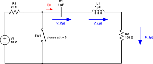
schematic

simulate this circuit – Schematic created using CircuitLab

I need to name the values shown in the circuit at t=0- (shortly before SW1 closes):

- i(0-)   = 0A (there is no current because C1 is blocking all DC Current after fully charged)
- V_C(0-) = 10V
- V_L(0-) = 0V (Complete Voltage at C1)
- V_2(0-) = 0V (Complete Voltage at C1)

Now I need to name the values shown in the circuit at t=0+ (shortly after SW1 closes); This is where I struggle:

- i(0+)   = ?
- V_C(0+) = 10V (Voltage cant jump at a capacitor)
- V_L(0+) = ?
- V_2(0+) = ?

I'm missing something really trivial here and would be thankful for some help.

\$\endgroup\$
2
  • \$\begingroup\$ What you have written is true; the voltage across a capacitor cannot change instantaneously. A similar thing holds for an inductor; the current through an inductor cannot change instantaneously. \$\endgroup\$
    – Carl
    Commented Jul 18, 2021 at 12:00
  • \$\begingroup\$ Yes, so would that mean that all the values at t=0- are the same as t=0+? \$\endgroup\$
    – Nik
    Commented Jul 18, 2021 at 12:01

1 Answer 1

3
\$\begingroup\$

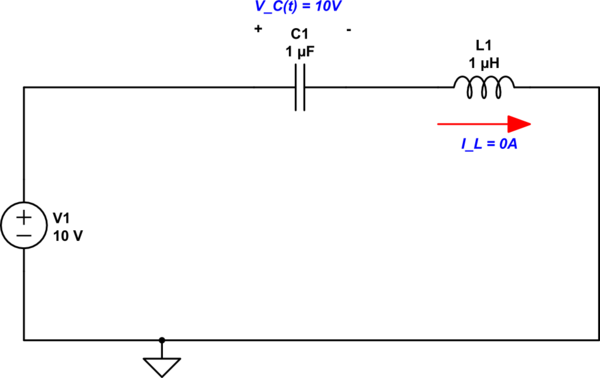
If the switch has been open for a very long time, then it's true that \$V_L=0\text{V}, \: I_C = 0\text{A}\$. This will result in the following circuit.

schematic

simulate this circuit – Schematic created using CircuitLab

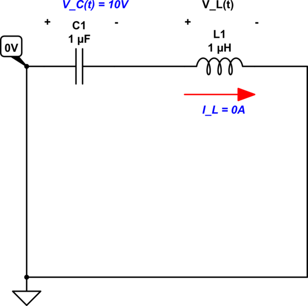
When you close the switch, you short out the voltage source and leave the energy storing components to discharge. The capacitor voltage and inductor current can't change instantaneously, so you know: $$V_C = 10\text{V}, \: I_L=0\text{A} $$ But one important thing to notice is that you also connect one end of the capacitor directly to ground. So now you have the following circuit.

schematic

simulate this circuit

You should be able to see that a thing regarding the voltage across the inductor has changed. I think this should be able to push you through the problem.

\$\endgroup\$
7
  • 1
    \$\begingroup\$ Thanks for your detailed answer. Just to clarify this means that now V_L(0+) = 10V? \$\endgroup\$
    – Nik
    Commented Jul 18, 2021 at 12:31
  • 1
    \$\begingroup\$ @Nik That depends on how you have defined the polarity of the inductor voltage. If you defined it like I have in the second circuit, then no. \$\endgroup\$
    – Carl
    Commented Jul 18, 2021 at 12:35
  • 1
    \$\begingroup\$ @Nik You got it. \$\endgroup\$
    – Carl
    Commented Jul 18, 2021 at 12:43
  • 1
    \$\begingroup\$ @Nik Well, I_L = 0A and so I_R2 = 0A. With Ohm's law V_R2 = I_R2*R2 = 0*R2 = 0. \$\endgroup\$
    – Carl
    Commented Jul 18, 2021 at 12:50
  • 1
    \$\begingroup\$ Well. Thats of course true.Thank you! I feel kind of dump now^^ \$\endgroup\$
    – Nik
    Commented Jul 18, 2021 at 12:53

Your Answer

By clicking “Post Your Answer”, you agree to our terms of service and acknowledge you have read our privacy policy.

Not the answer you're looking for? Browse other questions tagged or ask your own question.