0
\$\begingroup\$

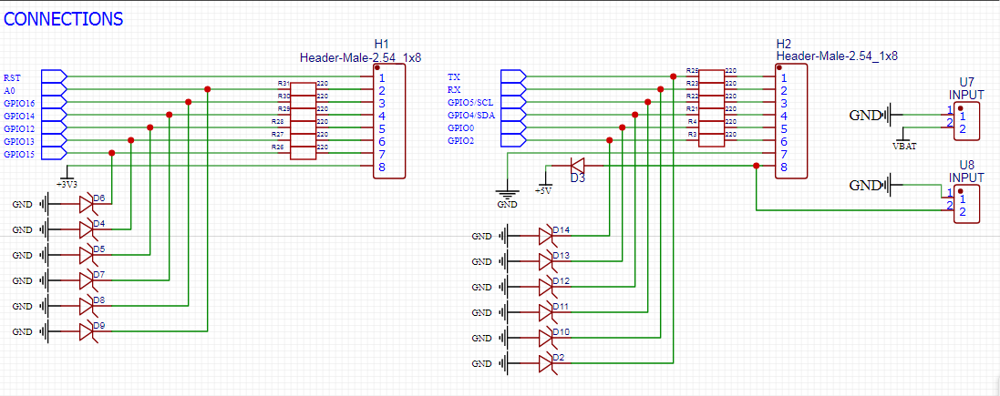
Is it possible to make this connection to an ESP8266 pin?

I saw this at Ruggeduino and tried to implement it for the ESP8266.

Below is the schematic:

enter image description here

Here's my reference:

enter image description here

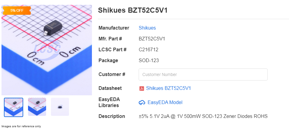
This type of diode:

enter image description here

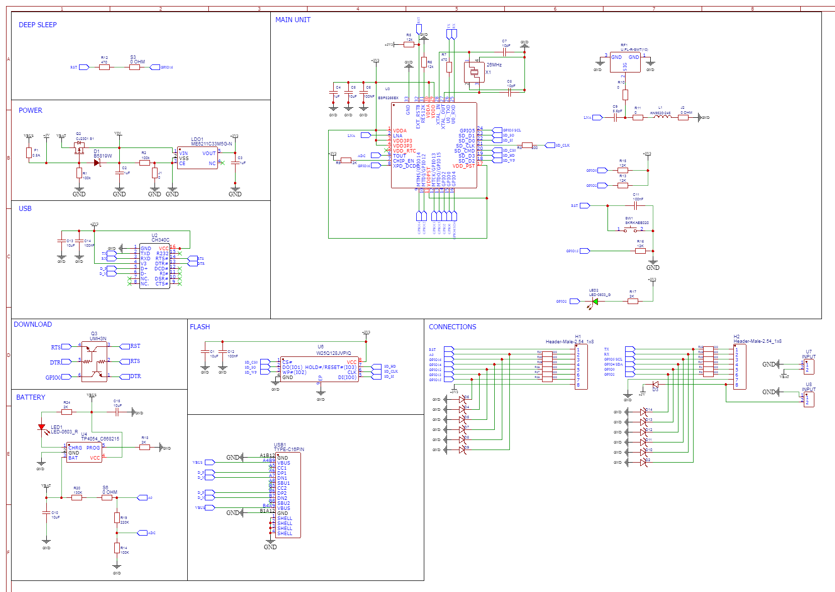
Here's my whole schematic:

enter image description here

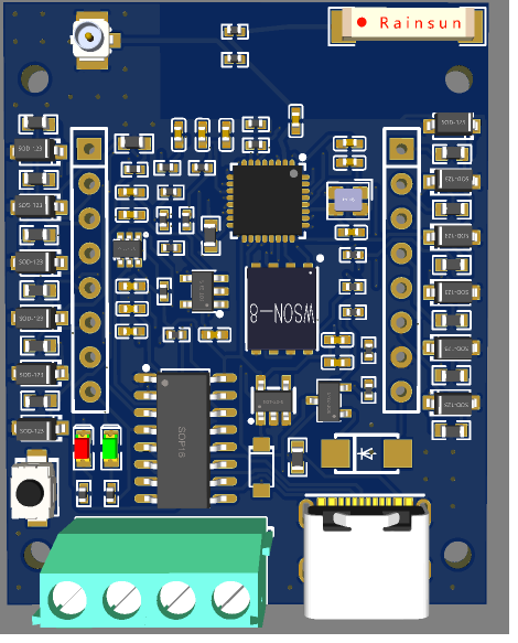
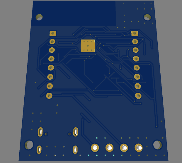
Here's the PCB looks like:

TOP SIDE

enter image description here

BOT SIDE

enter image description here

\$\endgroup\$
6
  • \$\begingroup\$ Please try to be a bit more specific about the diodes. As is it I don't seen anything strange except for the diode. If the wrong kind is used you may pull too much current from the GPIO. What is the exact model you plan to use ? \$\endgroup\$
    – Blup1980
    Commented Jul 29, 2021 at 12:18
  • \$\begingroup\$ i've been update my question to give some details, \$\endgroup\$ Commented Jul 29, 2021 at 12:26
  • 1
    \$\begingroup\$ What are you intending to do with that circuit? Also that's a 5.1V zener. The 3.3V IO on ESP would be toast long before the zener starts to conduct. \$\endgroup\$
    – Justme
    Commented Jul 29, 2021 at 12:36
  • \$\begingroup\$ just want to make io more safe, i seen at ruggeduino ( arduino industrial use ) website for this schematic and try to implemented to esp8266 \$\endgroup\$ Commented Jul 29, 2021 at 12:42
  • 1
    \$\begingroup\$ I wouldn’t be using the ruggeduino as the gold standard. Realistically, you shouldn’t be running gpio out into the real world without some form of signal conditioning. That is where you’d add the protection, not right on the gpio. \$\endgroup\$
    – Kartman
    Commented Jul 29, 2021 at 12:55

1 Answer 1

0
\$\begingroup\$

That topology works for 5V and above, but 3.3V Zener diodes are pretty sloppy. They have very soft knee and they vary a lot on when they will start conducting.
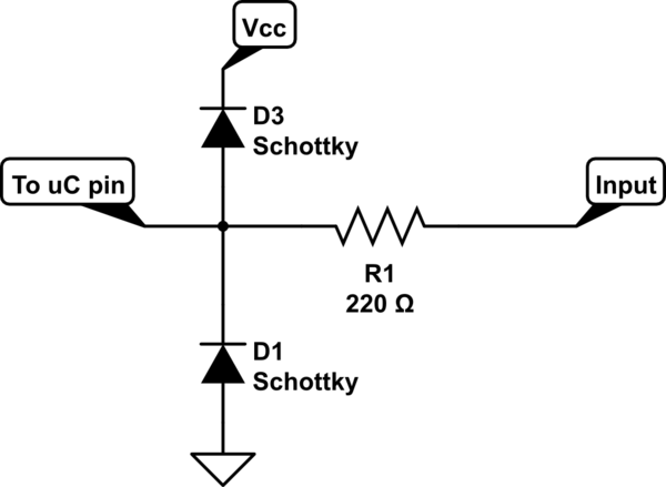
A better approach at this and lower voltages would be to use two Schottky diodes connected to the power rails.

schematic

simulate this circuit – Schematic created using CircuitLab

\$\endgroup\$
13
  • \$\begingroup\$ thank you so much for the answer, so i just need to add more diode like your schematic right ?... and is it okey to use same type diode ? \$\endgroup\$ Commented Jul 29, 2021 at 13:16
  • \$\begingroup\$ Yes, use the same diode part number in both positions. \$\endgroup\$
    – Aaron
    Commented Jul 29, 2021 at 13:26
  • \$\begingroup\$ sir, i've been upload my complete schematic, if you're not busy, would you check if there have somethings wrong. thanks. \$\endgroup\$ Commented Jul 29, 2021 at 13:31
  • \$\begingroup\$ @RizkisWalker That is way too tiny of a schematic to read. Upload it the way you did the first schematic, where I can click and get a larger view. \$\endgroup\$
    – Aaron
    Commented Jul 29, 2021 at 13:46
  • \$\begingroup\$ the picture now can be enlarge \$\endgroup\$ Commented Jul 29, 2021 at 15:01

Your Answer

By clicking “Post Your Answer”, you agree to our terms of service and acknowledge you have read our privacy policy.

Not the answer you're looking for? Browse other questions tagged or ask your own question.