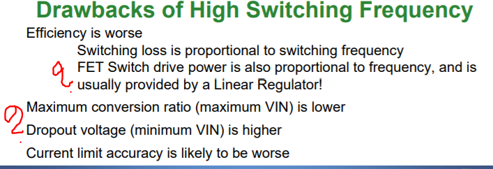
As per the below document https://www.onsemi.com/pub/Collateral/TND388-D.PDF higher switching frequency has the drawbacks listed. Iam unable to understand
-
6\$\begingroup\$ This is just a terminology nit- 'LDO' is not the same as 'linear regulator'. LDO means low dropout (linear) regulator. All LDOs are linear regulators but not all linear regulators are LDOs. Fairly often I see LM7805 and AMS1117 referred to as LDOs. The latter is arguably not, the former definitely not. \$\endgroup\$– Spehro 'speff' PefhanyCommented Aug 4, 2021 at 19:04
-
2\$\begingroup\$ Those are some pretty general statements in that presentation. There's no date on it either. Analog Devices has a slew of switching regulator components that make a lot of those statements/slides irrelevant. \$\endgroup\$– AaronCommented Aug 4, 2021 at 19:05
-
\$\begingroup\$ yeah, that presentation is ... questionable on points. Maybe ignore it. \$\endgroup\$– Marcus MüllerCommented Aug 4, 2021 at 19:09
-
1\$\begingroup\$ Wow, those are some dubious, sweeping statements right there. \$\endgroup\$– Simon FitchCommented Aug 4, 2021 at 20:02
2 Answers
The components inside a buck converter need to be powered to run, and since they are semiconductors they need to be powered from something stable (or at least not so high a voltage they will burn out).
But how does the converter start up then? It can't use its own output to power itself since it doesn't exist yet on startup. So inside it has a small linear regulator to power its various components, like the logic, voltage references, gate drive supply which in turn provides the primary power to the gate driver circuit.
A linear converter is either bulk unregulated or regulated.
The low output impedance smoothly rises on the output due to reduced gain, but then paralleled with caps that lower with rising f. This serves to avoid the intricate failures of not having a low source impedance at intermediate frequencies with load regulation noise interfering with the secondary regulator.
The statement only indicates linear sources are common, but to me it implies to high demand surge pulses, it is also preferred for low interference between RF input noise and the second converter.
Here they are referring to the high frequency switching rates around > AM band 1.5 MHz vs lower rates such as 50kHz and comparing the performance differences without getting into the complexities of chaos when a Buck converter with PWM drives a boost regulator using PFM.
They do exist as long as long as the intermediate impedance is a very low ESR cap and satisfy stability step-response requirements and decouple switching noise.

