0
\$\begingroup\$

The problem

I've got an industrial controller that takes an N-type thermocouple and scales its range (0-1300°C) to a 0-10V DC output signal. (For reference, the module is this: https://www.status.co.uk/product/signal-conditioner-temperature/)

The 0-10V signal has 200Hz noise coupled to the output. I would like to remove the noise.

I've tried using a low pass filter but it does absolutely nothing. The values of components used for the low pass filter are R = 787 ohms and C = 1uF giving me (roughly) a 200Hz cut-off frequency.

Analysis

The 0-10V signal is fed directly into a op amp in a unity buffer configuration (the op amp is an Analog Devices ADTL084ARUZ.) The signal is then passed into an acquisition system which is sampling the signal 10,000 times a second.

There are no other noise issues on any of the other analogue input signals for this system and I've changed the acquisition for an equivalent system so I know there are no issues with the acquisition itself.

The signal travels from the signal conditioning module to the acquisition via a screened 2 core cable over a distance of about 3 metres.

The question

What can I do to remove the noise?

I appreciate I could make the capacitor bigger therefore making the reactance lower and creating a quicker path to ground for the coupled noise signal. I suppose I could change the filter for an LC filter or a band pass filter as well.

Additionally, what is the best type of capacitor to remove these types of noise issues? I'm currently using a ceramic capacitor but I've also tried MLCC and electrolytic just to see if they would have a different effect but they also did nothing.

\$\endgroup\$
9
  • 5
    \$\begingroup\$ Off topic but out of curiosity: what application requires (and gets useful results from) a 10 kHz sampling rate for temperature? \$\endgroup\$
    – TypeIA
    Commented Aug 6, 2021 at 16:44
  • 4
    \$\begingroup\$ Well, with a single pole filter and a cutoff or 200 Hz, the best you could expect would be a 3 dB improvement in the noise. Since you're sampling at such a high rate a digital filter would be possible and effective. Barring that, a multiple pole analog filter with a cutoff of a few Hz might work, assuming you don't need fast response from your measurement for some reason. \$\endgroup\$
    – John D
    Commented Aug 6, 2021 at 16:51
  • 4
    \$\begingroup\$ 10kHz sampling for a slow changing temperature readout seems like overkill. It would be more reasonable to use a much lower sampling rate and let the antialiasing fliters kill the 200Hz signal. \$\endgroup\$
    – JRE
    Commented Aug 6, 2021 at 17:38
  • 1
    \$\begingroup\$ Where the noise comes from? Typically you would have 50/60Hz, so what is the source of 200Hz. Try in a different environment, to see if the noise disappears or might the conditioner itself can be the source. Then it's very important to know if the thermocouple tip is tied to GND or it is isolated, some conditioners won't work correctly. Does the conditioner has a galvanic isolation, to break a possible ground loop. Draw a schematics on how you wired it. \$\endgroup\$ Commented Aug 6, 2021 at 17:40
  • 1
    \$\begingroup\$ Have you tested the unit isolated from its current environment to make sure that the noise is not due to a faulty unit? \$\endgroup\$ Commented Aug 6, 2021 at 18:30

4 Answers 4

1
\$\begingroup\$

This is well possible, even with a first order RC filter that you use: You should set the cutoff frequency much below 200 Hz to get good attenuation at 200 Hz. e.g. 10...100 kOhm and 1 uF.

In addition, you can use digital filters as your sampling rate is very high.

While the Twin T notch filter has good attenuation, this is very sensitive to component values. Caps often have as much 20% tolerance and more over temperature, so building a good (nuch better than a simple low pass) Twin T notch filter is much more involved than it looks on paper.

\$\endgroup\$
1
  • \$\begingroup\$ Thanks for your feedback. Like I mentioned to Tony, the current build is quite tight so actually fitting a notch filter in may be quite difficult. The devil really is in the detail when it comes to filtering as I've quickly realised. I guess blanket assuming a 3dB attenuation would be enough was a bit silly really. I'll give some of the solutions presented here a go on Monday when I'm back in the lab and let you know how it goes. \$\endgroup\$
    – CT123
    Commented Aug 6, 2021 at 19:46
1
\$\begingroup\$

There are many ways to attenuate noise depending on source impedance, load and range of noise and signal.

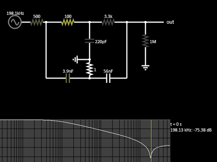
Given temp is near DC or say << 1Hz and noise is near 200 Hz +/- TBD %, one can use a notch filter with RC components and tune depth and centre frequency of the filter.

enter image description here

  • -76 dB attenuation at 200 Hz
  • -50 dB at 100 Hz
  • 0 dB at DC with a 500 ohm burden load for 20 mA max scale. of 10V

To design ANY LPF + Notch filter you need specs at least;
Rs source impedance
Rl load impedance (high)
f passband BW
f bandstop centre and attenuation min. @ band stop BW.

\$\endgroup\$
2
  • \$\begingroup\$ Thanks for your solution Tony. With such a high amount of attenuation I can see why this would be a much better solution to the problem at hand. I understand from the really helpful comments above from the other engineers that I've essentially been using a -3dB attenuator so the noise will be present for most "standard" first order filter configurations. The difficulty I have now is the module is in a place with limited space so as a first trial, I may try lowering the sample rate and see if the antialiasing handles the noise. \$\endgroup\$
    – CT123
    Commented Aug 6, 2021 at 19:18
  • 1
    \$\begingroup\$ Replace 787 with 33k for 33 dB attenuation \$\endgroup\$
    – D.A.S.
    Commented Aug 6, 2021 at 19:32
1
\$\begingroup\$

I don't know how you're processing the digital data, but if you average over any integer number of cycles of the noise, you will essentially eliminate it.

Clarification: assuming the noise is fairly periodic at 200 Hz, then the period is 1/200s = 5ms. You're sampling at 10kHz, so there will be 50 samples in every 5ms cycle of noise. By averaging 50 samples (or 100, or 150, or 200, ...) you will average out the noise. Obviously, this lowers your effective sample rate by 50 (or 100, or 150, ...) but you still have not justified sampling temperature at 10kHz. :)

Better yet, find the source of the 200Hz noise and eliminate it.

\$\endgroup\$
0
\$\begingroup\$

You have what looks like a good quality galvanically isolated thermocouple input signal conditioner.

You should ground the thermocouple at one place if (and only if) it is not already grounded at the junction. Grounding it at two places will cause the thermocouple to read incorrectly. For example, jumper the (-) lead of the thermocouple to the (-) lead of the voltage output. Otherwise common-mode noise can be picked up.

If that fails, another possibility is some ground issue in the signal chain. Without a complete schematic it's hard to speculate. Typically that might be at 50Hz or 100Hz in a 50Hz country, but maybe something else is going on. 200Hz is not a commonly encountered noise frequency.

\$\endgroup\$
2
  • \$\begingroup\$ "200Hz is not a commonly encountered noise frequency." Could it be some naval or avionic system? IIRC on (some) ships and/or planes they use AC power with higher frequency than "mainland" 50/60Hz. \$\endgroup\$ Commented Aug 7, 2021 at 5:32
  • \$\begingroup\$ @LorenzoDonati--Codidact.com Typically 400Hz (or sometimes "wild frequency" which varies with the turboprop RPM). Maybe there's something that uses 200Hz but I've personally not run into it. \$\endgroup\$ Commented Aug 7, 2021 at 5:38

Your Answer

By clicking “Post Your Answer”, you agree to our terms of service and acknowledge you have read our privacy policy.

Not the answer you're looking for? Browse other questions tagged or ask your own question.