0
\$\begingroup\$

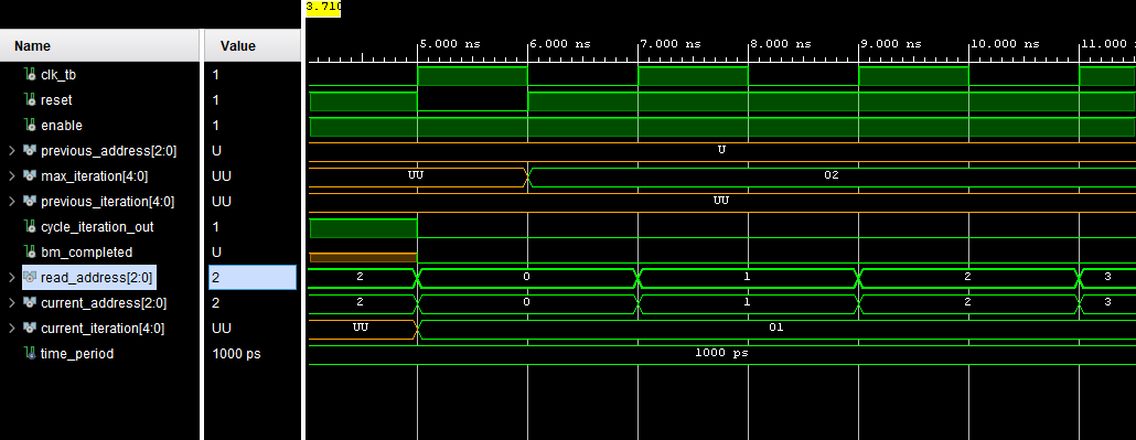
how do you test circuits with output signals which feedback into the input circuit? Below is an example of a test bench i wrote, the current_iteration and current_address should feedback into the inputs of previous_iteration and previous_address. However in the simulation it shows that the inputs are basically uninitialized shown by U.

How to solve this problem, would creating another entity which transfers the output signals into the inputs work?

enter image description here

library IEEE;
library work;
use IEEE.STD_LOGIC_1164.ALL;

entity addr_iter_tb is
end addr_iter_tb;

architecture Behavioral of addr_iter_tb is
    
        --Clocking signals
        signal clk_tb : std_logic:='0';
        constant time_period : time:= 1 ns;
        
        --Stimulus signals    
        signal reset: std_logic:='1'; --Active low reset
        signal enable: std_logic:='1'; --By default enabled
        signal previous_address: std_logic_vector(2 downto 0);
        signal max_iteration:  std_logic_vector(4 downto 0);
        signal previous_iteration: std_logic_vector(4 downto 0);
        
        signal cycle_iteration_out: std_logic;
        signal bm_completed: std_logic;
        signal read_address: std_logic_vector(2 downto 0);
        signal current_address: std_logic_vector(2 downto 0);
        signal current_iteration: std_logic_vector(4 downto 0);

begin

    addr_iter_instance : entity work.addr_iter port map (
        clk=>clk_tb, reset=>reset, enable=>enable, previous_address=>current_address,
        max_iteration=>max_iteration, previous_iteration=>current_iteration,
        cycle_iteration_out=>cycle_iteration_out, bm_completed=>bm_completed, 
        read_address=>read_address, current_address=>current_address,
        current_iteration=>current_iteration
    );
    
    clocking_process : process begin
        wait for time_period;
        clk_tb <= not clk_tb;
    end process;
    
    stimulus_process : process begin
        wait for 5 ns;
        reset <= '0';
        wait for 1 ns;
        reset <= '1';
        enable <= '1';
        max_iteration <= "00010";
        wait;
    end process;

end Behavioral;
\$\endgroup\$
8
  • \$\begingroup\$ Just create a signal in the TB and assign it to both component ports that need to be connected. \$\endgroup\$
    – Eugene Sh.
    Commented Aug 11, 2021 at 18:34
  • \$\begingroup\$ I have done that in the test bench, it doesnt work \$\endgroup\$ Commented Aug 11, 2021 at 18:41
  • \$\begingroup\$ Then it doesn't work for some other reason. \$\endgroup\$
    – Eugene Sh.
    Commented Aug 11, 2021 at 18:44
  • \$\begingroup\$ Does it work for you? What version of Vivado are you using? \$\endgroup\$ Commented Aug 11, 2021 at 18:48
  • \$\begingroup\$ Nobody else can test it without the DUT, where the problem almost certainly lies, and which only you have. Is its "current_address" port an OUT port and its "previous_address" an IN port for example? Is the driver for that OUT port initialised on RESET? Do all the signals contributing to that driver have the correct values? Examine what's happening INSIDE the DUT. \$\endgroup\$
    – user16324
    Commented Aug 11, 2021 at 18:54

2 Answers 2

2
\$\begingroup\$

Both DUT ports Prev_Address and Curr_Address connect to signal Curr_Address, and work fine, delivering the Curr_Address output to the Prev_Address input of the DUT.

Signal Prev_Address in the TB is simply unused. No initialisation, no drivers, no assignments to it.

What you're displaying as "UU" is just a redundant signal, not the Prev_Address input port value (which is the Curr_Address signal)

If you insist on seeing a value on it, Pre_Address <= Curr_Address; in the concurrent region of the TB. And then you could map the Prev_Address port to the Prev_Address signal, in the port map.

But, best solution : just delete it.

And if you want to see the values on the input port Prev_Address, learn enough Vivado simulator to find its "add signal addr_iter_instance/Prev_Address to Wave Window" command or menu option.

\$\endgroup\$
13
  • \$\begingroup\$ What simulation are you using and do you mind showing some pictures of it working? Im using Vivado so it could be different \$\endgroup\$ Commented Aug 11, 2021 at 20:47
  • \$\begingroup\$ This is not sim dependent and I'm not going to sim it. Plus, see update (coming) \$\endgroup\$
    – user16324
    Commented Aug 11, 2021 at 20:49
  • \$\begingroup\$ So how do you know it works then? lol \$\endgroup\$ Commented Aug 11, 2021 at 20:50
  • \$\begingroup\$ a quarter century experience using VHDL count for anything? lol \$\endgroup\$
    – user16324
    Commented Aug 11, 2021 at 20:51
  • \$\begingroup\$ Okay so what simulation tool have you used which shows the correct values for the current feedback structure. In, Out ports, and a signal connection \$\endgroup\$ Commented Aug 11, 2021 at 20:53
0
\$\begingroup\$

That is another thing I had, very long long time ago. So, I forgot how I managed, but throwing a random thoughts (again). Please pardon me of using incorrect terminologies.

Since, you do not want to connect the signals internally;

  1. Can the simulator take multiple "modules" and route the signals between modules (named signal)? Then you may use a module that passes signals around.
  2. Can the to-be-simulated module become a sub package, so the signals can be routed through the top module?
\$\endgroup\$
2
  • \$\begingroup\$ Yes it can take multiple modules. Im not sure about the second \$\endgroup\$ Commented Aug 11, 2021 at 19:23
  • \$\begingroup\$ @LinusMagnola that is a good news! I will use that when time comes. Thanks. \$\endgroup\$
    – jay
    Commented Aug 11, 2021 at 19:26

Your Answer

By clicking “Post Your Answer”, you agree to our terms of service and acknowledge you have read our privacy policy.

Not the answer you're looking for? Browse other questions tagged or ask your own question.