If you can't put parallel termination of the signal at the receiver side, then you can use source-series termination to match the impedance at the source side.
Also suppose that the FPGA output impedance is less than 50ohm. I have
learned it from an IBIS model. Therefore in theory I can match an
impedance with one series resistor on the source side.
You are correct. If the driver has output impedance Z_driver and the transmission line has output impedand Z_line, then add series termination Z_term = Z_line - Z_driver. The series termination resistor should be placed as close to the source as possible.
But the 50-ohm line width on a 0.4mm FR4 is 0.73mm, and the pitch of
the LQFP-144 is 0.5mm.
This is only true for a specific layer spacing and dielectric constant. Its possible to purchase PCBs with different dielectric constants, or adjust the spacing between layers to get what you want. Typically narrowing the traces or increasing layers spacing will increase impedance, and widening traces or decreasing layer spacing will decrease impedance.
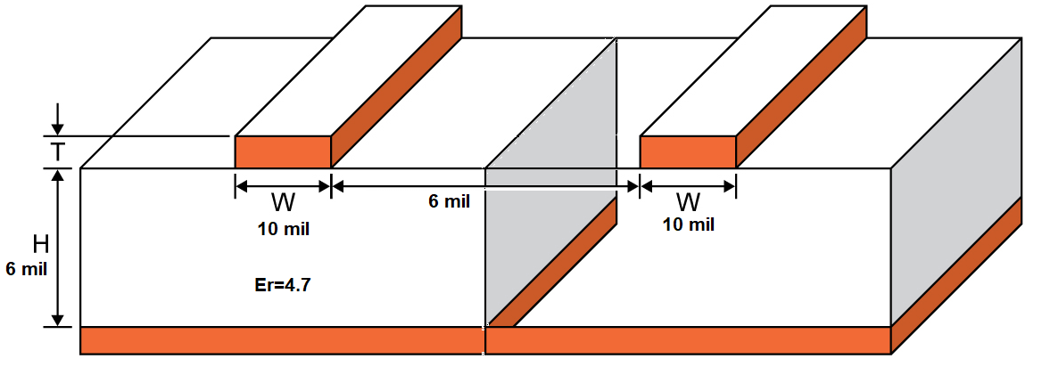
For example, 1oz, 10 mil traces, with 6 mil to the ground plane, and Er=4.7 gives 49.7 ohms impedance on a microstrip impedance calculator and will fit in a 0.5mm pitch. There are a lot of manufacturers, including inexpensive ones, that can make something similar.
https://www.allaboutcircuits.com/tools/microstrip-impedance-calculator/

But also keep in mind that with the traces so close together you are likely to get cross talk. So its better to just spread them apart anyways if you can. Typically you would want the trace to trace separation to be several times the trace to ground-plane separation.
So, my impulse will run towards the load. Then it will reflect off and
run to the 50-ohm connector on PCB, then it will reflect off from the
connection of PCB line and 50-ohm connector despite any of my
impedance matching actions.
Having the wrong impedance for a very short run is typically OK. So if the distance to the connector is very short then it should be fine to just run the traces at 0.5mm pitch to the connector (except for the issue of cross talk mentioned above). If its not very short then you should use whatever method you can to spread out the traces as soon as possible, and run them at 50 ohms for as much of the distance as you can.
It should be noted that if you are going to add series termination resistors you will probably have to spread out the signals anyways. Even an 0402 size SMD resistor is about 0.5mm wide, and there needs to be clearance between them and the adjacent traces. The only way you could keep the traces at 0.5mm center to center with termination would be to go to really tiny resistors like 0201 or use use some of the multi-resistor packages that are designed for termination.

