2
\$\begingroup\$

I am referring to a microstrip PCB transmission line. I simulated the crosstalk situation using Hyperlynx.

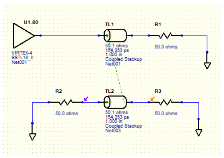
Please see the below circuit:

enter image description here

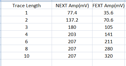
I kept increasing the trace length and measured the crosstalk at R2 (near end) and R3 (Ffar end.) Many values are given below.

enter image description here

What I observed is after some time the near-end crosstalk amplitude is constant. It stops changing with trace length.

Its amplitude remains constant.

How does the near-end crosstalk saturate?

\$\endgroup\$
2
  • \$\begingroup\$ Please be more specific in your question (provide more details) \$\endgroup\$
    – Voltage Spike
    Commented Aug 23, 2021 at 20:32
  • \$\begingroup\$ I updated the question. Could you please check it \$\endgroup\$
    – Confused
    Commented Aug 25, 2021 at 15:00

2 Answers 2

2
\$\begingroup\$

Near end cross talk (NEXT) saturates because the coupled signal or energy propagates backwards on the victim trace back towards the source.

For a trace longer than the rise (or fall) time of the signal, each segment of trace, or each transmission line segment couples to the adjacent trace, but in different locations. So the individual coupled pulses from different segments of the trace reach the near end (source) at different times. The net results is that the NEXT is stretched out in time, but at a constant amplitude.

The text "High-Speed Signal Propagation (Advanced Black Magic)" by Drs. Howard Johnson and Martin Graham does a good job of explaining this, on pages 318-321.

Added graphics and some more detail

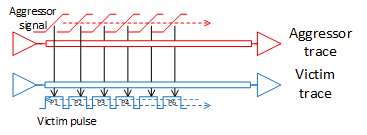
The picture below tries to illustrates this problem.
enter image description here

Red shows the leading edge of a signal on the aggressor trace as it propagates along the trace. Blue shows the coupled noise pulses on the victim trace.

These pulses travel both left (towards the source) and right (towards the destination) along the victim trace. At the destination end (far end), the pulses all arrive at approximately the same time and so add in magnitude. The longer the traces, the more pulses there are to add , which is why the FEXT increases with trace length.

At the source end (near end), the pulses arrive in a time sequence fashion, P0, then P1, P2, etc. So at the near end, the crosstalk signal increases in time with trace length, but not amplitude (once it reaches its nominal value).

enter image description here

Keep in mind that this is not a discrete phenomenon as the graphic might suggest. The coupled pulses are continuous along the length of the victim trace, occurring spread out in time as the signal edge propagates down the aggressor trace.

\$\endgroup\$
4
  • \$\begingroup\$ "the individual coupled pulses from different segments of the trace reach the near end (source) at different times".This includes both inductive coupled current and capacitive coupled current. At the near end side, they are summing Ic+IL.To become constant the amplitude of capacitive coupling and inductive coupling should be the same when the trace length is longer than rise time.But how they are becoming equal? \$\endgroup\$
    – Confused
    Commented Aug 26, 2021 at 5:59
  • 1
    \$\begingroup\$ I'm working on a graphic to help illustrate this. But, it's not an Ic vs IL thing. It's a time delay effect. If the pulse on the victim net from the first transmission line segment arrives back at the source at time T0, and the pulse from the second transmission line arrive back at the source at T0+delta, then those two pulses don't add up in magnitude (since they're arriving at different times), but rather stack against one another in time to as to lengthen the pulse at the victim source. \$\endgroup\$
    – SteveSh
    Commented Aug 27, 2021 at 13:03
  • \$\begingroup\$ Thanks SteveSh...I am eagerly waiting for the graphic.I am sure it will be very helpful. \$\endgroup\$
    – Confused
    Commented Aug 27, 2021 at 13:06
  • \$\begingroup\$ Thank you for the graphic.One question ,why at the destination end (far end), the pulses all arrive at approximately the same time and at the source end (near end), the pulses arrive in a time sequence fashion \$\endgroup\$
    – Confused
    Commented Aug 28, 2021 at 16:51
1
\$\begingroup\$

This has puzzled me for quite a while too. My take of it is as following. The near end experiences a slow charging process because the testing point has been accumulating charge since time zero. That is why its voltage shape mimics a capacitor. On the other hand, the far end does not experience any charges/voltage until the electromagnetic (EM) wave arrives at the testing point, which is at the very end of the line. By then, the previously quiet line has already been fully charged, indicating constant resistance. That is why its voltage shape mimics its current shape.

\$\endgroup\$

Your Answer

By clicking “Post Your Answer”, you agree to our terms of service and acknowledge you have read our privacy policy.

Not the answer you're looking for? Browse other questions tagged or ask your own question.