2
\$\begingroup\$

I am looking into building a calibration kit for HV differential probes.

The approach I take is to inject the square wave at the input of the differential probe and trim the trimmer caps to compensate the probe till the signal at its output represents the attenuated signal at its input.

This proves challenging considering some probes have an attenuation factor of 1000 or 500. Considering that most signal generators are capable of a maximum peak output voltage of 10 V it means that the outputs signal level is very low.

I drafted some desired specifications, However, none it is a must.

Specifications:

  • V(peak) = 1 kV
  • f = 1 kHz
  • V(ripple) = 1 V
  • T(rise) = 1 μs

So far, I have considered using a ±1000 V DC source and an H-bridge. I have not done much HV design, though I have studied power electronics so I have some basics. As usual, details matter therefore before diving into the H-bridge idea. I prefer to ask as very often a design that works on paper is a nightmare to implement.

I did not post any specific questions as I am more looking for suggestions of things to consider before I begin the design process. Perhaps there are already existing modules that I could use.

\$\endgroup\$
4
  • 3
    \$\begingroup\$ What is your question? \$\endgroup\$ Commented Aug 24, 2021 at 11:38
  • \$\begingroup\$ 1. My question is what other method I could use? 2. Would the H bridge be doomed from the start as I did not factor in real-world component limitations? 3. Are there any "ready-made" solutions? \$\endgroup\$
    – Wintermute
    Commented Aug 24, 2021 at 12:52
  • \$\begingroup\$ You have HV opamp apexanalog.com/products/pa194.html unfortunately max. +/-450V max. \$\endgroup\$ Commented Aug 24, 2021 at 13:58
  • \$\begingroup\$ @MarkoBuršič thank you! Excellent suggestion. As much as I would prefer to achieve a peak voltage of 1KV I might have to compromise. \$\endgroup\$
    – Wintermute
    Commented Aug 24, 2021 at 14:02

3 Answers 3

2
\$\begingroup\$

1000 V / us is very fast, approximately the same risetime as Shottkey TTL. At that high a voltage, a very small amount of stray capacitance will have a real impact on the risetime. Compared to a 10 V signal, the total energy required to charge up stray capacitance will be 10,000 times greater.

Also, transistors with high voltage ratings have high collector-to-base capacitance, which acts as a integrator to slow the collector rise and fall times. The first challenge will be to find transistors rated for over 1000 V that are fast enough.

\$\endgroup\$
2
  • \$\begingroup\$ Thank you for your comment. I will have to reconsider the rise time. \$\endgroup\$
    – Wintermute
    Commented Aug 24, 2021 at 12:57
  • \$\begingroup\$ @Wintermute Look for CRT horizontal sweep BJTs. Those have to deal with high voltage and fast sweep rates. \$\endgroup\$
    – jonk
    Commented Aug 24, 2021 at 18:16
0
\$\begingroup\$

Your 1kV spec is difficult.
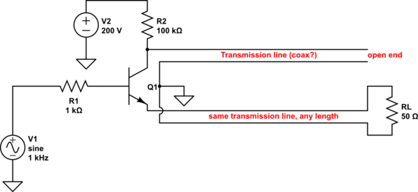
A suggestion here for a high-voltage pulse generator having fast rise/fall time of perhaps 1 ns. It might manage something like 100V pulse height. It uses an avalanche transistor.

Many rather ordinary transistors can achieve avalanche operation when you push them past their base-to-collector \$BV_{cbo}\$ with a high supply voltage - naturally a current-limiting resistor is required to prevent smoke. When collector-base avalanches, the transistor is ready to switch very quickly...when base is raised above emitter, the transistor turns on. So a low-voltage signal generator can trigger a very fast switch-on. Switch-off occurs naturally when the transmission line empties into \$R_L\$. Most circuit simulators fail to capture this behavior.

schematic

simulate this circuit – Schematic created using CircuitLab

Transmission line length at transistor collector sets the output pulse width. Load resistor RL must match transmission line impedance with some precision, to keep pulse top flat - important for your application. Low-loss transmission line recommended...you might try higher impedance than 50 ohms - I've used that only for convenience.
Choose a large collector resistor to keep avalanche current low. At 1kHz, it must charge the open-end transmission line capacitance up past the transistor's avalanche voltage in one millisecond. Output to calibrate your probe is taken across RL.

\$\endgroup\$
0
\$\begingroup\$

For this function, you don't need 1 kHz signals. So, for simplicity you can use a relay to switch the signal. Use a small (say 0.1 uF) decoupling capacitor on the output of the 1 kV source, and switch this signal to your probes with a large (~ 1 MΩ) to ground.

This will give fast rise time, not falltime, but if the probe's calibration is linear, this is sufficient.

Be careful with 0.1 uF charged to 1 kV -- that's a dangerous amount of energy. Use a discharge resistor (also 1 MΩ) across that component. You will need resistors and capacitors rated for that voltage. If you don't understand the concepts, don't play with 1 kV; it can be fatal.

\$\endgroup\$

Not the answer you're looking for? Browse other questions tagged or ask your own question.