The easiest way to control a relay with any microcontroller is via a MOSFET. You have two choices, one is to try and drive the MOSFET directly from the Jetson output pin or use a chip that helps drive the MOSFET.
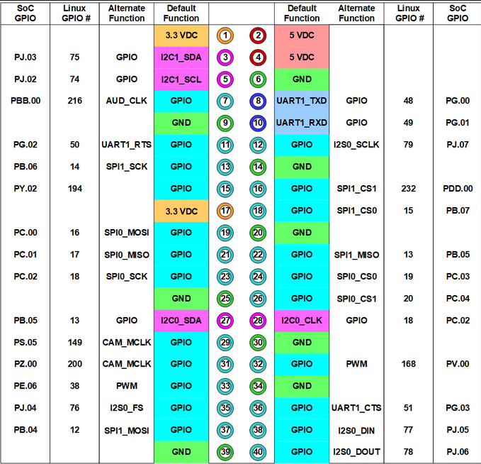
The output pins of the Jetson are either 3.3V or 1.8V, so your best bet is to go with the 3.3V outputs. Each pin can produce 1 mA which is plenty for driving a MOSFET.
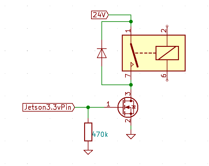
When driving the MOSFET directly, you must identify a MOSFET that can be driven by such a low voltage (3.3V). You don't specify how much current the 24V relay needs, but as long as it is under 300 to 400mA, there are plenty of parts to select from. Look for a MOSFET that is tagged as "logic level" or similar, such as the DMN62. The circuit would look like this:
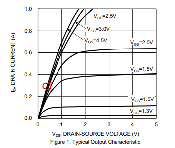
 You will have to be careful and ensure that the MOSFET "opens up" enough with the low voltage. For example, this is the Drain-Source voltage versus current for the specific MOSFET (DMN62). I have circled the operating point assuming a 300mA relay so the voltage across the MOSFET will be about 0.4V and power dissipation of 0.12Watts. The particular MOSFET can dissipate up to 0.3Watts so you are ok but the thermal resistance is pretty high so expect a 50-degree rise in its temperature which is kind of high. All of this can change of course, once you plug in your relay current requirement.

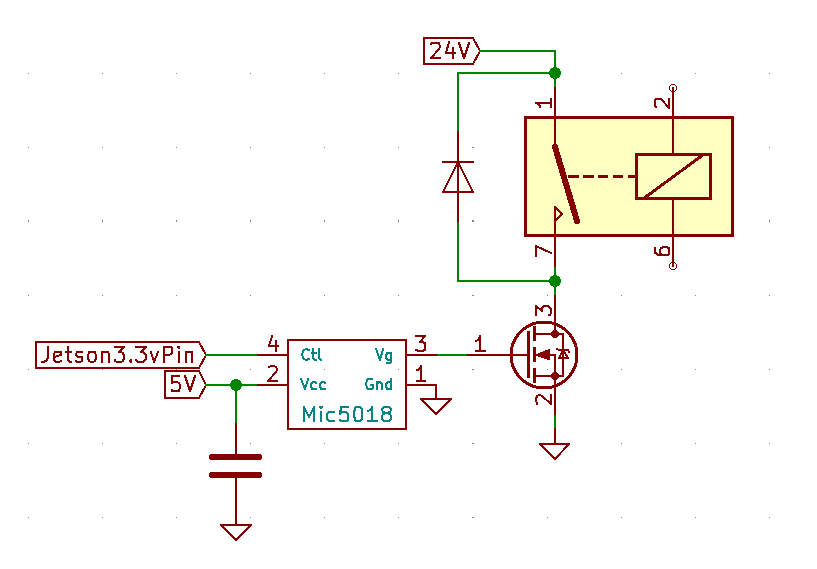
The second option is to use a driver chip that can generate a gate voltage that is much higher than the controlling voltage. One example of such a chip is the MIC5018, which even when powered at 5V (which you have available from the Jetson rail) will generate a gate voltage of about 15V. And it requires at most 1 microAmp of current at its input. That will allow you to use just about any MOSFET that has proper voltage and power characteristics. In this case, instead of a 'logic drive" MOSFET, just look for a part that has the lowest Drain-Source resistance when fully driven. You could operate just about any relay with the proper MOSFET in this case. The circuit would look like this.


