0
\$\begingroup\$

Every reputable antenna book that I've read says that dipole antennas are resonant at integer multiples of a half wave length.

Wikipedia describes resonance as:

the phenomenon of increased amplitude that occurs when the frequency of a periodically applied force is equal or close to a natural frequency of the system on which it acts. When an oscillating force is applied at a resonant frequency of a dynamic system, the system will oscillate at a higher amplitude than when the same force is applied at other, non-resonant frequencies.

For a dipole to me this means that resonance occurs when an AC source is applied with frequency that has a wavelength which allows an increase in the amplitude of the standing wave on the antenna to occur, because the applied source "tops up" the circulating energy at exactly the right moments, due to the resonant length.

Everyone knows that a center fed resonant 1/2 wave dipole has a feed point impedance of about 70 ohms with no reactance.

There is no reactance because the length of the elements results in the current of the standing wave at the center feed point being in phase with the applied source, and the voltage of the standing wave at the feed point (which is always about 90 deg out of phase with the current of the standing wave everywhere on the antenna), is at the zero cross over point and so contributes no reactance to the feed point impedance.

So the impedance is low with no reactance.

My understanding is that only for a resonant dipole does there exist any points where if split at those points and used as the feed point there will be no reactance.

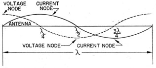
For dipoles which are odd multiples of a 1/2 wave of the frequency of the applied source in length, the points where there is no reactance are at the current maximums or current loops, because it is at those points that the current is in phase with the applied votage source and the out of phase voltage is at the zero crossing point.

For a full wave dipole with feed point at the center, the voltage of the standing wave at the feed point is in phase with the applied source and at a maximum value, whereas the current is 180 deg out of phase with the source but at the zero crossing point.

This means the feed point impedance is high with no reactance.

enter image description here

To me it seems that a full wave dipole is a resonant antenna, and if the feed point is in center it has a high non-reactive impedance.

There is of course an under-current in between the lines of this question, and that is the idea that reactance in the feed point impedance does not always mean not resonant, or in other words, a resonant antenna can have reactance in the feed point impedance, it just depends on where along the antenna length the feed point is. In fact it seems that resonance together with no reactance in the feed point impedance is the exception rather than the rule.

What am I missing?


Moderator Note: The same question was asked here at Amateur Radio.SE so interested readers may want to visit that page too. To avoid any appearance that this situation is the norm, duplicating questions across different SE sites is generally strongly discouraged.

\$\endgroup\$
4
  • 1
    \$\begingroup\$ Could the context be resonant versus anti-resonant? The term anti-resonant might apply to the feed-point where impedance is high. Equating non-resonant with anti-resonant is a big mistake. \$\endgroup\$
    – glen_geek
    Aug 29, 2021 at 2:27
  • \$\begingroup\$ "Anti-resonant" is definitely a better term. It really means "resonant but in a way I don't find useful". I don't know what the feedpoint impedance of a full-wave dipole would be, but I do know that folks have made them, using quarter-wave sections of 300\$\Omega\$ or 600\$\Omega\$ parallel-wire feedline to bring their impedance to something not terribly mismatched to 50\$\Omega\$ coax. \$\endgroup\$
    – TimWescott
    Aug 29, 2021 at 4:33
  • \$\begingroup\$ @glen_geek Thanks for the comment, i agree with you totally, it seems pretty obvious that resonance and reactance in the feed point impedance don't always occur together, in fact resonance with no reactance in the feed point is a special case and is the exception, not the rule. \$\endgroup\$
    – Andrew
    Aug 29, 2021 at 4:50
  • \$\begingroup\$ @TimWescott i agree totally ! \$\endgroup\$
    – Andrew
    Aug 29, 2021 at 4:50

3 Answers 3

1
\$\begingroup\$

There are several versions of definitions of resonance.

  • lumped elements store energy and maximimize this behavior at resonance.
  • Transmission lines at resonance just look like resistance,
    • either matched (half wave) or reflected to ground reference ( quarter wave) and their respective multiples of wavelength.
    • or conjugate mismatched such as a 1/4 wave notch filter by impedance inversion.

So the conflict of assumptions is that non-resonant antennae do not store energy and yet energy storage elements can radiate through non-resonant wires.

But in effect all standing wave antenna have perfect resonance and those that reflect some back to the source are imperfect resonators.

The assumptions require context to resonance with a reactive gain above unity or a passive amplifier with the ideal being conjugate reactance cancelling to result in a resistive load.

Viz. A non-resonant antenna is made resonant with the conjugate matched impedance. this is the case for AM coil antennae with very high Q for voltage amplification.

\$\endgroup\$
2
  • \$\begingroup\$ So are you saying that a full wave dipole is not a resonant antenna ? Can you explain further ? There are other modes of resonance apart from the commonly referred to "series resonance" ? ... Resonance to ground ? ... \$\endgroup\$
    – Andrew
    Aug 29, 2021 at 5:34
  • \$\begingroup\$ I say that all multiples of 1/4 wave are resonant but RF guys know the type that tune with T or L filters and call these resonant antenna, but it's a resonant system with a non-ideal or non- resonant antenna in order to transform impedance to reduce wire losses. Just the opposite... but here the context is lumped element resonant antenna \$\endgroup\$ Aug 29, 2021 at 6:46
1
\$\begingroup\$

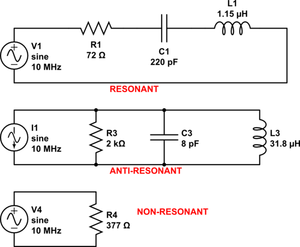
Consider the lumped-element equivalent of a resonant antenna. Over a narrow frequency range (from a wavelength slightly longer than half-wave to a wavelength somewhat shorter than half-wave), real current goes through a maximum. Reactive current goes through zero, changing sign.

In the series circuit current goes through a maximum at resonance. This circuit would be equivalent to feeding a resonant half-wave dipole at its center. We call this a resonant antenna.
Note that if we feed this series circuit with a current source (where current is constant-amplitude), voltage at its terminals would go through a minimum at the same frequency. If we have a minimum at a certain frequency, the term used might be anti-resonant.
Go figure - in this series-circuit, we prefer the voltage-source feed rather than current-source feed, since we most often describe a series-circuit as resonant. Same for the center-fed half-wavelength dipole.

The parallel circuit shown has a maximum impedance and maximum voltage at anti-resonant frequency. This circuit might be equivalent to feeding a half-wavelength wire at one end, with respect to earth. A one-wavelength wire, fed at its center would have roughly similar impedance and voltage trends. Is it proper to call a one-wavelength wire, fed at its center a "dipole"? This arrangement would best be described as anti-resonant.

A non-resonant antenna would be resistive at all frequencies - something difficult to achieve in a universe with finite speed-of-light. In our universe, impedance of free space is 377 ohms.

schematic

simulate this circuit – Schematic created using CircuitLab

\$\endgroup\$
1
\$\begingroup\$

I hope it's not bad form to reply at this late date, but there are a few issues I did not see directly addressed. First, any radiator of a capacitive type antenna (not just a dipole) is resonant at any integer multiple of a 1/4λ in length, not just integer multiples of a 1/2λ; and in the case of a 1/2λ dipole, it might be useful to think of it as 2 colinear, end-fed 1/4λ antennas with differential voltages at their feed-points. It's the fact that each element is 1/4λ in length that makes the element's feed-point impedance as low as 73 ohms. If each element were an even multiple of 1/4λ, i.e. 1/2λ, 1λ, 1-1/2λ, 2λ, etc. the feed-point impedance would be very high (as in 2500-3000 Ohms) because a voltage applied at those multiples are attempting to enter the radiator at a voltage node, and therefore have to overcome the reflected voltage of the previous cycle, which is in phase at 360 degrees; this is in contradistinction to any odd multiple of a 1/4λ element, i.e. 3/4λ, 1-1/4λ, etc., where the applied signal encounters one of the previous cycle's reflections at 180 degrees out of phase, which is a low impedance, and a current node. In either even or odd multiples of a 1/4λ element, the higher the multiple, the more toward a mean impedance the antenna will have; in otherwords, the impedance of odd multiples of a 1/4λ will increase with lengthing, and the impedance of even multiples of a 1/4λ will decrease with lengthing, as the reflected voltages decrease, whether in-phase in the case of even multiple, or out-of-phase in odd multiples.

So as far as a Full Wave Dipole, it is really 2 colinear, end-fed 1/2λ antennas with differential voltages at their feed-points; and as such, as long as the feed-point voltages are differential, you can expect nearly double the gain of a 1/2λ dipole. Final note, for those who don't feed their 1/2λ dipole with a differential voltage source, as in someone using unbalanced line, like coax cable with no BalUn, the antenna isn't a dipole, it's simply a 1/4λ antenna with a counterpoise. As a side note, a center-fed Full Wave Dipole would be the preferred way to co-phase 2-1/2λ antennas as bandwidth would be a little greater, and the radiation pattern would certainly be more omni-directional than two 1/2λ elements, end-fed at one end and phased with a delay segment into the next 1/2λ element, since the delay segment would also radiate/receive and create some distortion the antenna's pattern. A coil could be used as a delay element, but while that might contain some unwanted radiation and may be better for the pattern, it would narrow bandwidth a bit more than a normal folded phasing element. Everything's a trade-off!

\$\endgroup\$

Your Answer

By clicking “Post Your Answer”, you agree to our terms of service and acknowledge you have read our privacy policy.

Not the answer you're looking for? Browse other questions tagged or ask your own question.