So in the forward bias cycle from 0-0.7 v diode should not conduct?
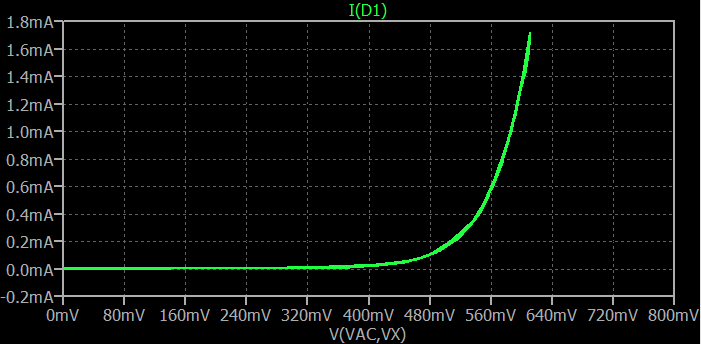
Strictly speaking, diodes follow an exponential curve with respect to the voltage across them. So it still does conduct current when the forward bias is less than \$700\:\text{mV}\$. It's probably worth keeping the following curve in mind:

The above was produced as a composite of multiple simulation runs through a 1N4148 diode model (an approximation of a real diode of that type.) You can see the very distinct nature of a diode's behavior as it gradually moves into increasing forward conduction.
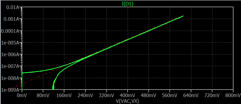
I just told you that this is an exponential curve. Well, not quite. Let's look at the above curve, but now drawn on a logarithm plot (of current):

(The above shows the green line bifurcating. Focus on the upper one. The one that dives downward is an artifact of some parasitics in the circuit. So it's not important here.)
Note that I've drawn a barely visible dashed red line that parallels most of the curve in the log(current) plot. The diode follows this line pretty well over many magnitudes of current, but at very low currents it deviates. So a diode is almost exponential over a wide range. But not quite.
It's actually an exponential curve with an offset to it. About where the red line intersects the y-axis is called the saturation current of the diode and it's one of the more important "model parameters" that help define a diode's behavior. The straight lines drawn for different diode families will intersect the y-axis at different places. Some higher, some lower than what you see there.
Who provides the forward voltage or knee voltage to start the diode
for rectification. I am assuming it is the AC signal that needs to be
rectified. Is that correct?
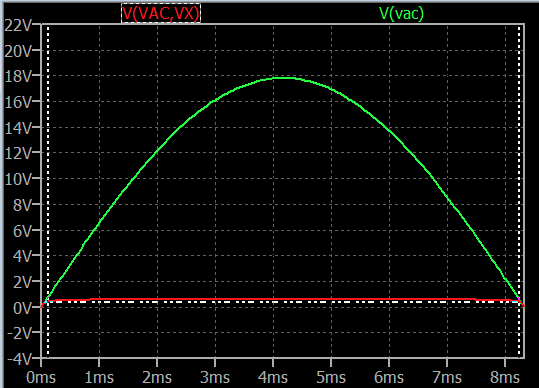
Yes, exactly! In half-wave rectification, only about half of the entire AC cycle causes the diode to be forward-biased. Here's a plot showing this behavior during one half of the AC cycle:

Note that I've drawn white dashed vertical lines about where the diode achieves a forward voltage of about \$400\:\text{mV}\$ (where it just begins significant conduction.) This is just inside, on either side, of where the AC sine wave itself rises upward. So the diode isn't conducting for the full half-cycle, but almost.
And you are right, that the source voltage's behavior, as applied to the diode circuit, is what stimulates the diode to conduct current.
Just keep in mind that there must be something also in the circuit to limit the voltage across the diode. The diode really does behave exponentially with respect to the forward voltage across it. So it's very damaging to the diode if you don't include something in the circuit to limit the current. (This actually means some way to limit the voltage across the diode, though.) In the above cases, I included a simulated \$10\:\text{k}\Omega\$ resistor.


