I'd like to find a hardware-based solution to make LEDs fade from digital pins. i.e. instead of switching on/off, slowly fading (500ms) into/out of full brightness. I can't imagine a small capacitor taking half a second to discharge... Ideally it would be in a nice DIP16 package so I can get an array of fading LEDs. Does my dream component exist?
-
\$\begingroup\$ Drive an LED from a triangle wave oscillator? \$\endgroup\$– MattyZCommented Feb 20, 2013 at 0:33
-
1\$\begingroup\$ If I program a microcontroller to do this, and put my own part number on the package and then sell it to you, does that count as a hardware solution? \$\endgroup\$– gbarryCommented Feb 20, 2013 at 0:49
-
1\$\begingroup\$ I appreciate that you'd take time out of your day to sell me a PWM script, but I was genuinely wondering if there is a component that could round-off a digital signal over 500ms without some form of oscillation. \$\endgroup\$– romCommented Feb 20, 2013 at 1:04
-
\$\begingroup\$ Theoretical, only. I went through the same thoughts and ultimately realized that at some level, a chip's a chip. However, you don't want oscillations, so that narrows the question. \$\endgroup\$– gbarryCommented Feb 20, 2013 at 1:39
-
\$\begingroup\$ Why without oscillation? \$\endgroup\$– starblueCommented Feb 20, 2013 at 6:43
5 Answers
The usual way to do this is to use PWM (Pulse Width Modulation)
Just about any modern microcontroller has a PWM peripheral that can be set up for this purpose. If you don't want to use a microcontroller, a dedicated PWM IC or a timer IC like the ubiquitous 555 can be used.
The process is simple, the pulse frequency is set fast enough so the human eye cannot detect flicker (typically above 25Hz - see Persistence Of Vision) and the time on vs time off is varied from 100% on (full brightness) through 50% on 50% off (half brightness) to 0% on (off)
Note that this can easily be used for an array, you simply supply the PWM to all the LED driver transistors (make sure the base current is adequate for bipolar, or use MOSFETs. Design choices would depend on what type of LED you are driving, high/low current)
Check on the 'net for "555 LED Fade" and you should get plenty of results. Here's one picked at random from here ( I haven't checked it so I can't confirm it works correctly) :
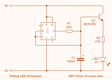
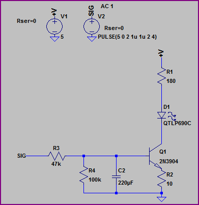
Alternatively, if absolute accuracy of timing is not so important, a simple option would be to use an RC filter and transistor switch. This way the cap doesn't have to supply the LED current, only the base current. Something like this:
Simulation:
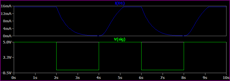
Any general purpose NPN should do, and you can tweak the R and C values to suit.
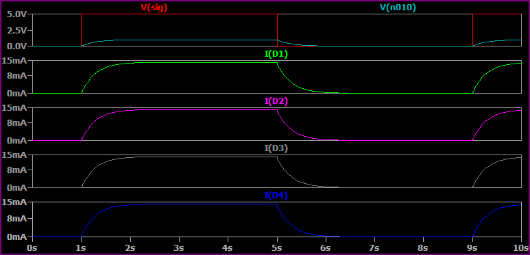
This option can easily be extended to an current mirror array with the addition of an opamp. This circuit should perform well as long as the transistors are all of the same type (supply used is +5V):
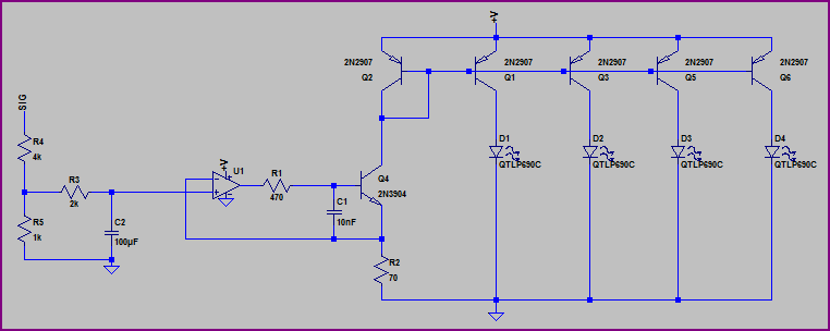
Simulation:
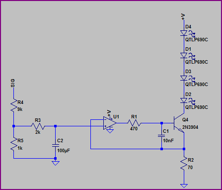
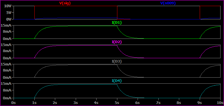
If you have a high enough supply voltage, the LEDs can go in series like this (supply used here is +10V):
Simulation:
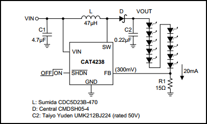
Alternatively, if you have a low supply voltage but want to drive the LEDs in series, there are lots of cheap boost ICs such as the CAT4238. This part can dim the LEDS using PWM or a varying DC voltage (details are in the datasheet)
-
\$\begingroup\$ Comprehensive answer, thank you. The RC setup is the closest to what I'm looking for, however LEDs fading out of sync with odd brightness levels doesn't sound promising. If I've got this right, would it not be possible to manufacture a self-contained IC with a variable resistor to change the RC value and ultimately adjust the fading time? \$\endgroup\$– romCommented Feb 20, 2013 at 11:41
-
1\$\begingroup\$ @rom - as long as the transistors are of the same type and matched pretty well, the circuit should function okay. However, if you are worried about this give me a little while and I'll post a similar option that won't suffer from this problem, and controlled by a variable resistor for fading time (we can make the fade linear also). \$\endgroup\$ Commented Feb 20, 2013 at 15:23
-
1\$\begingroup\$ @rom - I altered the circuits for more stable versions. Any of these should be suitable. The series options would be the best option if you have the supply headroom, but the parallel current source will be fine as long as you use the same transistors will reasonably well matched gains (if you have a transistor tester, you can hand pick them if you wish, but the current difference will be small anyway, and likely not enough to be visible) I added an IC example - you might want to have a look through all the other options too. \$\endgroup\$ Commented Feb 20, 2013 at 16:38
How's this?
The FAN5646 is a flexible and compact solution for a blinking/fading LED.
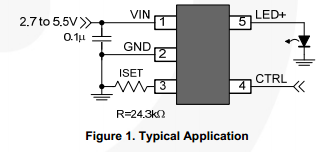
-
\$\begingroup\$ That is an interesting chip. I will need to sample that. Sweet find dextorb \$\endgroup\$– PasserbyCommented Feb 20, 2013 at 4:44
You could use a small cap + big resistor to generate a nice long charge characteristic (t=RC), then feed that into the base of a transistor and drive the LED from there.
This allows for a bigger resistance since the current through the LED isn't limited by the resistor size, and then you can use a small cap.
It would be necessary to bias the transistor so that it's being used as an amplifier (if it hits saturation, then the LED will just stay on).
If by a digital pin you are using an output from some type of processor, it is possible to change the brightness in firmware. As you change the duty cycle of the pin, the eye acts like a filter and perceives a shorter on time as a dimming in brightness.
1 - Use a PWM pin output instead of a digital GPIO pins. By changing a few registers you can change the on time of the LED and thus the brightness.
2 - Use a timer (polled or interrupt) to change the state of your pin.
3 - Use external shift register ICs to latch the on/off times of n LEDs. Though this requires more programming effort, it is extensible and uses fewer GPIO pins than (1) and (2).
PWM LED Drivers. They need configuration from a microcontroller though. 555 Timer + a few resistors and caps can do the same, no software needed.
