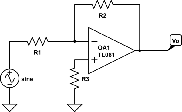
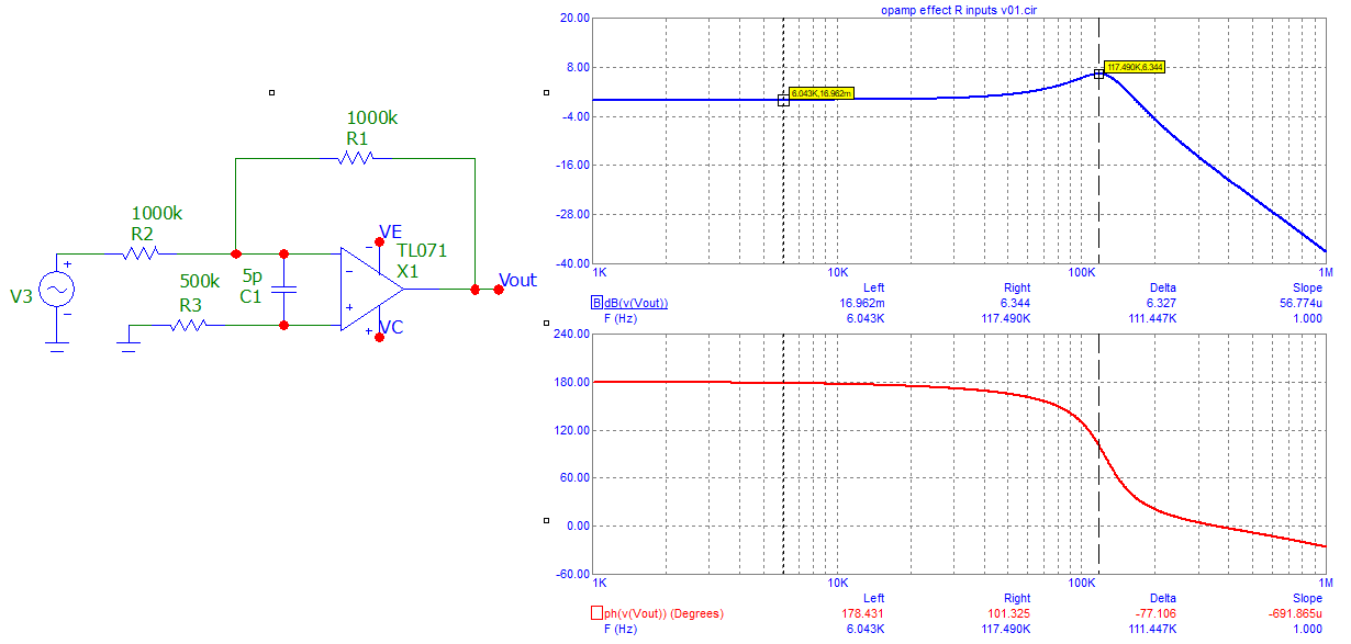
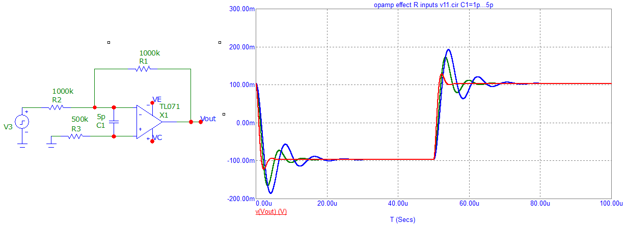
I'm trying to figure the effect of adding a resistance at the non-inverting input of a inverting amplifier.

simulate this circuit – Schematic created using CircuitLab
How can introduce it in the derivation of the transfer function?
I understand that when there is a voltage source at the non-inverting input and the resistor it makes the voltage level at both inputs are the same (like some kind of clip.)
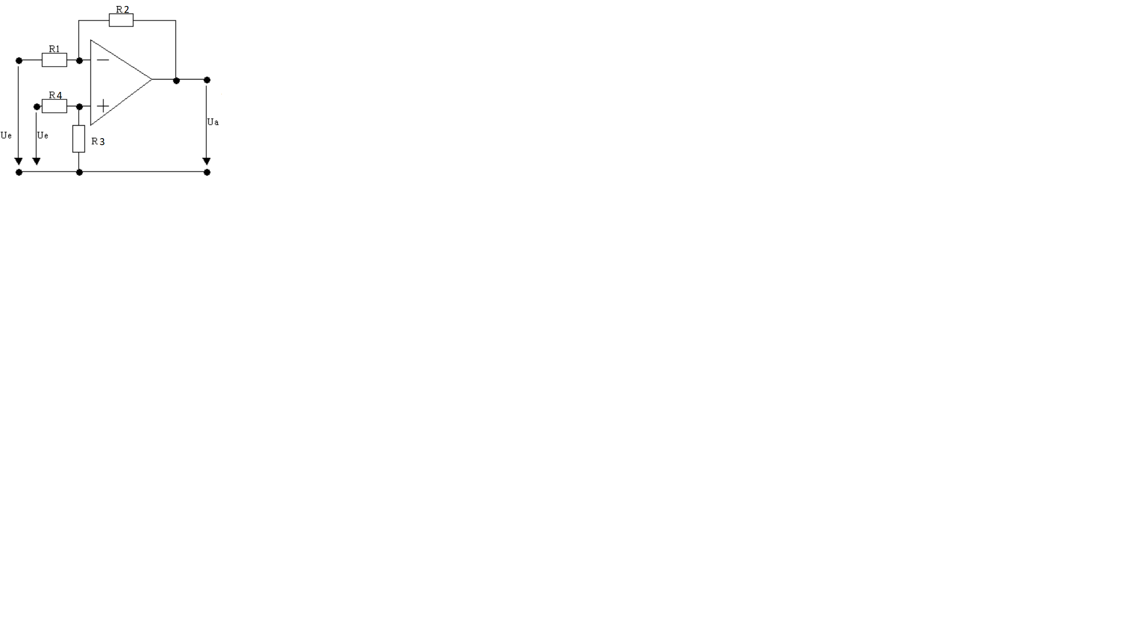
In this case if there is voltage source in the + input.
\$I_{+}=\frac{0-V_{source}}{R_{3}}=0A\$
since there is no current entering the op-amp, but in the case of the diagram, how can represent the + input in math form so it can be added to the derivation of the standard non-inverting amplifier?


