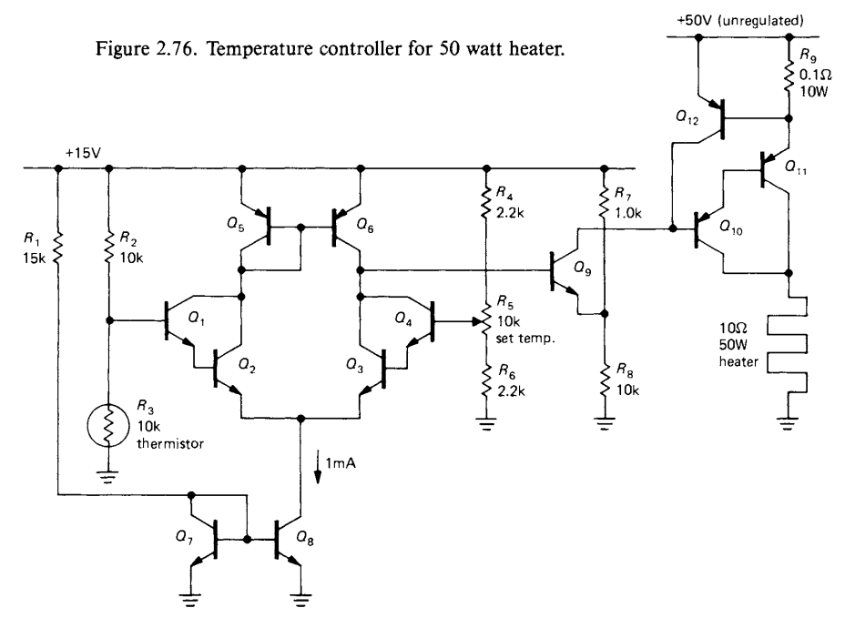
If I were going to EE school, then there would be a lot of knowledge transferred just by going through all of the usual things -- labs, homework, exams, etc. In teaching myself, it's so hard when they just "Q1, Q2, Q3, ..." and I know that the choice of the individual transistors requires further decision making, and I can easily do it wrong. I wish they would place a more fully worked-out instance on a later page, sort of like a reference design.
Specifically, can I use jellybean 2N3904 and 2N3906 for Q1-Q8, the comparator-like subcircuit? Or do I have to use a dual (like PMBT3904YS,115) or a matched pair (like DMMT3904W-7-F)?
What follows are my semi-educated guesses. Though I'm not really completely sure which transistor to start with.
I would feel comfortable using the jellybean 2N3904 and 2N3906 for Q9 through Q12. Perhaps Q10 could be a 2N4401 -- it depends on how much we need to saturate Q11. Though I would put Q10 a distance from Q11 to separate it thermally and hopefully improve performance. And I would put a 2SA1908 at Q11, or some other power-transistor with a heat-sink.
Anyway, that's my current, probably somewhat divided view of what I would do, mixed with what I think might be required.
2.22 Temperature controller -- The schematic diagram in Figure 2.76 shows a temperature controller based on a thermistor sensing element, a device that changes resistance with temperature. Differential Darlington Q1-Q4 compares the voltage of the adjustable reference divider R4-R6 with the divider formed from the thermistor
and R2. (By comparing ratios from the same supply, the comparison becomes insensitive to supply variations; this particular configuration is called a Wheatstone bridge.) Current mirror Q5-Q6 provides an active load to raise the gain, and mirror Q7-Q8 provides emitter current. Q9 compares the differential amplifier output with a fixed voltage, saturating Darlington Q10-Q11, which supplies power to the heater, if the thermistor is too cold. R9 is a current-sensing resistor that turns on protection transistor Q12 if the output current exceeds about 6 amps; that removes base drive from Q10-Q11, preventing damage.
(Added emphasis mine.) The preceding excerpt is from page 105 of The Art of Electronics, Second Edition, by Horowitz, Paul; Hill, Winfield. Cambridge University Press. Kindle Edition of hardback (ISBN 978-0-521-37095-0):
Note: I am trying to teach myself -- this is not homework or school work. A software developer trying to gain more knowledge of hardware so I will write better firmware.

