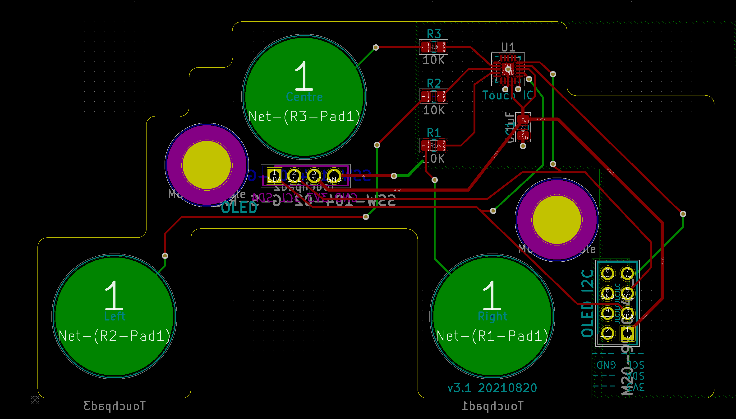
Would greatly appreciate any expertise/suggestions on solving this problem! In particular have I done anything glaringly stupid when it comes to my PCB design??
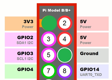
I'm trying to get touch control working with an OLED screen, controlled by a Raspberry Pi Zero W. This is via a custom PCB for touch & OLED, connected via a short (~5cm) ribbon cable from the first 8 pins of the Pi. The Pi has built-in 1k8 pull-up resistors on the SDA & SCL lines.
The screen is an SSD1306 screen running over I2C (using luma.oled), it's worked well for a few months when used in conjunction with touch control using an AT42QT1070 in standalone mode with three keys tied to GPIO pins. However I’m now putting the setup in a plastic enclosure and the sensitivity in standalone mode isn’t sufficient to detect the touch, therefore I need to run the touch controller in comms (I2C) mode (I2C), as that lets you adjust the sensitivity.
i2cdetect shows both devices fine (0x3c for the screen, 0x1b for the touch controller). I have a Python script to control the screen and another for touch control. However I'm now finding if I load the screen script it will start the screen and update fine but then after a few seconds it will then crash out with an I/O error. I've tried a different screen but no change and if I put it back on an old board (similar design but with the touch control in standalone mode) it works OK.
It seems that if I just run with the screen connected or just with the touch controls it works OK (I can interrogate the registers, pull touch sensor readings, etc.) but when both are connected I'm running into issues, despite both showing up correctly and both working to some extent before they abort.
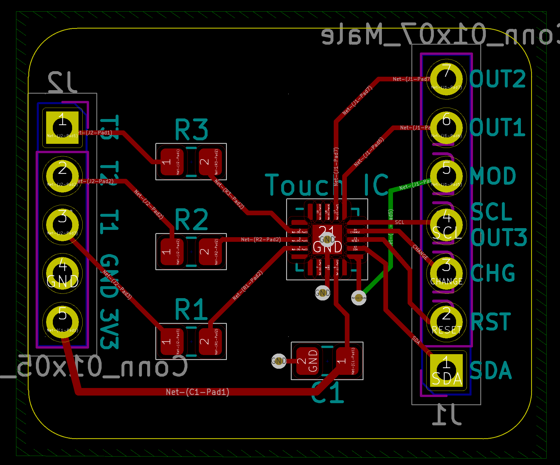
On my breadboard layout (I created one for this VQFN package - unfortunately the larger 14-pin SOIC I had used previously seems to be out of stock thanks to the worldwide chip shortages!) they seem to both work OK at the same time, so I’m worried I’ve done something stupid with my PCB design! As I say I can interrogate the registers on the AT42QT1070 OK, it’s more like something destabilises the I2C bus when I’ve got the screen running too?
My KiCAD PCB layout for the main board is attached (the weird board outline is due to other components/fixings in the case I have to work around), I've also attached the breakout I designed for the breadboard. Both are standard 2-layer FR4 boards, manufactured by JLCPCB.
I've read through the NXP/Philips I2C design spec as well as the Atmel touch control guidance and have tried to balance things as best I can - e.g, no ground plane around the touch controls, cross touch over other lines at 90 degrees, short ribbon cable from Pi to this PCB. I'm wondering if I need a different routing of the I2C SDA/SCL lines or more ground plane around them? Should I run separate connections for these lines from the IDC pins to the OLED and to the touch controller rather than join them en route as I've done here? I've not quite worked out how to calculate parasitic capacitance, etc. but can't imagine I've gone above the 400pF limit with just two slaves and fairly narrow/short traces? Unfortunately I don't have an oscilloscope which I understand would be helpful to look at the signals better and see if there are any issues there.
Please just say if any more info would be useful and thanks in advance for any help!…


