0
\$\begingroup\$

Logic input in logic circuits can be on, off, or disconnect. In the last case, there is "floating logic" issue, inductance and electromagnetic noise causes current in logic parts that may be missintepreted as "on". For this reason, logic circuits are usually designed to avoid "disconnect" circuits.

On to "pull up resistor" concept. I find the terminology to be a bit contradictory. This guy claims that the strongest "pull up" is actually a zero resistance part, https://youtu.be/u3Xiy2DVnI4?t=59. And, that some resistance is added to avoid short circuiting. He also claims that too much resistance causes same effect as "disconnect". The truth of both these claims is corroborated by Googling around a bit.

This seems to me to mean that "pull up" is more a circuit design (to avoid "disconnect" state with "floating" logic), and that a resistor is just introduced to, like I suggested in topic of this question, avoid wasting current when the circuit would short circuit (unless there was some resistance added to the voltage supply. )

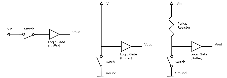
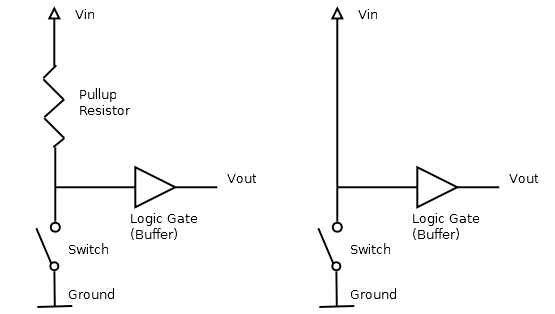
To illustrate it, the examples below both solve "floating" issue. Because there is no "disconnect state" (both made the design choice to define an open (off) switch, as logic high voltage, preventing the floating issue, a design choice that is unintuitive if "floating" was not an issue. ) But one has no resistor. It will short circuit at logic low, burning electricity unnecessarily. Seems to be why a resistor is added, not to remove "floating", but to make the design that does so work better.

enter image description here

To me it makes 100% sense if the “pull up” is the design choice to make logic high voltage the default when the input switch is off, specifically to resolve the issue of “disconnected” circuits that will have noise, “floating”, and that the “pull up resistor” is something that has to be added because that “inverted circuit” will short circuit at logic low otherwise, something the “uninverted” circuit, see below, the intuitive circuit to use if "floating was not an issue", would not.

enter image description here

What I find hard to understand as a beginner was that the resistor itself was “pulling up” anything, since, well, it doesn’t. The resistor is given all sorts of meaning and "agency" that it does not have. It pulls nothing up. It just makes a "pulled up" design not short circuit. Perhaps obvious to someone good at this, but, the concept of "pull up resistors" often confuse people, so this is what I found unclear in how it was usually explained.

To avoid any ambiguity, below are illustrations step by step. The second circuit is what does what people generally say the resistor does. I add resistor in figure 3, where circuit was already "pulled up" at figure 2 step. The resistors only role is to avoid the short circuiting at logic low that is a consequence of using the "pull up" circuit design (no such problem in circuit 1 below. )

enter image description here

To be absolutely 100% clear in what I ask:

The “pull up” seems to be a design choice to force a logic high voltage when the input switch is “off”, to prevent the result of treating input switch “off” as logic low voltage, a “disconnect” that leads to floating logic issue. The “pull up resistor”, seems to be added to the “pull up” design pattern, exactly to prevent burning electricity when the input switch is “on” and the circuit would be shorted, not travelling through the “resistor” of the logic component the output goes to.

In my head, "pull up" is the logic inversion forcing the logic high at input off (that would otherwise be a "disconnect" state), the reverse of what people would use if floating issue did not exist. And the "pull up resistor" is added to the "pull up" to avoid shorting at the logic low.

Thanks for all feedback in the many comments and helping me (probably) understand what a "pull up resistor" is for. Also, here is another person making the exact same case I am making here, for why "pull up resistors" are explained in a way that makes it hard to understand, https://www.youtube.com/watch?v=BxA7qwmY9mg&lc=UgiXxV6C427_iXgCoAEC.

\$\endgroup\$
2
  • \$\begingroup\$ All - The long comment chain has exceeded what is reasonable for comments, and has become a discussion. Therefore it has been moved to chat and should be continued there (link below). --- As this bulk moving of comments to chat can only be done once per question, any further comments posted here might be deleted without notice. Keep it in chat, please! New answers can still be added, as usual. Thanks. \$\endgroup\$
    – SamGibson
    Commented Sep 15, 2021 at 16:34
  • \$\begingroup\$ Comments are not for extended discussion; this conversation has been moved to chat. \$\endgroup\$
    – SamGibson
    Commented Sep 15, 2021 at 16:35

5 Answers 5

4
\$\begingroup\$

To answer the question in the original title - almost always "no", it's not to drop the voltage. The role of a pull-up resistor is to make sure an input to a logic element isn't left "floating" when nothing else is driving it.

Suppose a logic block A has an output feeding into the input of B. What happens if A is switched off, disabled, or not outputting anything for some other reason? The input to B could be high, low, or some intermediate voltage that isn't even a valid logic level.

Connecting a resistor between the power rail and the input to B ensures that it will always be pulled high if nothing else is driving it. It has to be a resistor, because A still needs to be able to change the voltage on B's input.

A strong pull-up has a low resistance, as it allows more current to flow. A weak pull-up has a high resistance. It's an engineering judgement what value resistor you need based on the characteristics of A and B.

Pull-down resistors are also a thing. They are used when you want an input to go low when nothing else is driving it.


Here's an example of where a pull-up resistor is useful. A couple of years ago, I was developing software to run on a rack of electronics. The rack had a backplane, into which you could plug processor cards.

One of the lines on that backplane was Reset. If it was high (around 3.3V), then all the cards in the rack would work as normal. If it was low, everything would halt. When the line went high again, all the cards would reboot.

That Reset line had to be at a well-defined voltage. If it was left floating, it could be high, low, or any voltage in between. If the voltage was in the undefined range between "high" and "low", everything could go haywire.

The designers of the backplane put a resistor between the 3.3V power line and Reset. In the absence of anything else, the Reset line was pulled high, and everything worked.

There was a push-button on the front of the rack. Pressing it shorted the Reset line to ground, resetting all the cards.

The designers of the rack included a handy "Reset" socket to the front of the rack. We made up a bit of electronics to drive a transistor connected between Reset and Ground. The electronics was driven by a USB port on a PC next to the rack. By turning the transistor on, then off again, I could reset the whole rack remotely, under software control. That was really useful for hands-off testing.

This only worked because of the pull-up resistor. Without the resistor, the Reset line would float to an undefined voltage. If the resistor had been replaced by a zero ohm wire link, then attempting to reset the rack would have shorted out the power supply and done some serious damage.

\$\endgroup\$
13
  • \$\begingroup\$ This guy claims that the strongest "pull up" is actually a zero resistance part. And, that some resistance is added to avoid short circuiting. This is what I suggested in the question. But, I skipped over "floating logic issue" that is the main reason to avoid "disconnected" circuit. So I get why every reply tries to explain that to me, but, maybe you also see what I mean is a bit contradictory with standard ways of explaining "pull up". youtu.be/u3Xiy2DVnI4?t=59 \$\endgroup\$ Commented Sep 15, 2021 at 12:14
  • \$\begingroup\$ @LearningBasicComputerScience I agree with what that video says. \$\endgroup\$
    – Simon B
    Commented Sep 15, 2021 at 12:54
  • \$\begingroup\$ Sorry, removed my last comment. I agree about the video explaining it pretty clearly. I don't get the confusion. \$\endgroup\$
    – StarCat
    Commented Sep 15, 2021 at 13:01
  • \$\begingroup\$ @StarCat I'm someone seeing all this for the first time. To me, it is much easier to think of it as that "pull up" is a design pattern that is distinct from the choice to add resistance. That the resistor forces "logic high" made little sense to me. But, that designing the circuit so that "input off" will force logic high voltage, instead of logic low like would be preferred if "floating" was not an issue, to resolve "floating", makes sense. It seems to be two separate issues, to my "noob" head. \$\endgroup\$ Commented Sep 15, 2021 at 13:12
  • \$\begingroup\$ As a noob, that "the resistor forces logic high", makes no sense. At all. But that forcing logic high by adding a voltage input that is what forces the logic high, makes sense. And that this is done to avoid "floating", makes sense. The actual adding a resistor seems to me, to just be to avoid short circuit issue. \$\endgroup\$ Commented Sep 15, 2021 at 13:13
2
\$\begingroup\$

Here's an analogy for a pull-down resistor.

enter image description here

Figure 1. A spring return ball valve. The photo shows the valve in the open position with the translucent copy of the handle being the closed position. Image source: Heco.

  • The spring is equivalent to a pull-down resistor in that it forces the input (the handle) into the off (logic low) position which will shut off fluid current (electrical current).
  • With a strong enough push on the handle (a low-enough resistance pulling the input high) the valve will open.
  • If the push on the handle is roughly equal to that of the spring (the pull-up = the pull-down) then the valve will be partially open (undefined open state).

The pull-up, pull-down concept is really very simple.

schematic

simulate this circuit – Schematic created using CircuitLab

Figure 2. Various options for preventing undefined logic levels.

  • (a) uses a double-throw (changeover) switch to switch the logic level between 1 and 0 and avoids pull-up or pull-down resistors. Note that during the break-before-make action that the logic is left floating and any stray interference may cause it to toggle enough to be read as alternating high and low. A small capacitor on the input of BUF1 would solve this. The downside is that many switch styles are not available in changeover versions and it adds unnecessary complication to the circuit.
  • (b) defaults to a logic low input and is switched high by SW3 closing. A single-throw switch can be used.
  • (c) defaults to a logic high input. This arrangement is very common because it can use switches but also open-collector or open-drain outputs which makes it very flexible.
  • (d) is just to say that this is not a "pull-up". The input is tied to V+. It may be used (without the switch) on spare / unused logic gates in a circuit to prevent undefined logic input levels which in turn may turn on both the high-side and low-side output transistor resulting in "shoot-through" and destruction of the chip. Closing SW5 will short-circuit the power supply.

The resistor is given all sorts of meaning and "agency" that it does not have. It pulls nothing up. It just makes a "pulled up" design not short circuit.

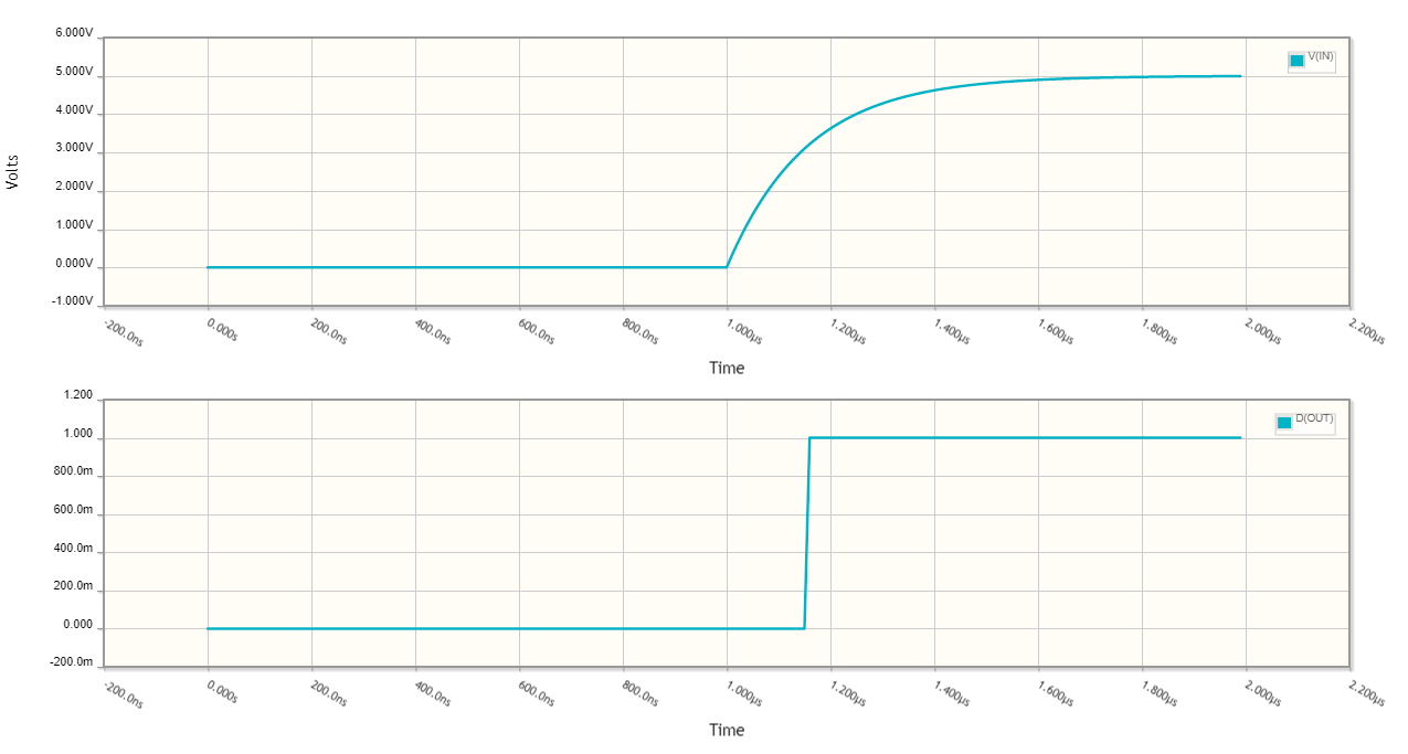
This is not true. The input to the logic gate can be modelled as having some capacitance in parallel with some resistance (extremely high for CMOS) and may source of sink some input leakage current. A pull-up resistor will charge the input capacitance and the voltage will rise to positive supply in the standard exponential RC charge curve. This will happen every time SW4 is opened in Figure 2c above. R2 pulls the input high.

schematic

simulate this circuit

Figure 3. CMOS input model with 15 pF parasitic capacitance. The switch is set to open at t = 1 μs.

enter image description here

Figure 4. The result of the simulation of Figure 3.

Here we can clearly see the pull-up effect of R1 when SW1 is opened. The time-constant is τ = RC = 10k × 15p = 150 ns. We can also see that this causes a delay on the buffer as it won't switch until about 2/3 supply.

My question originally pointed out that the resistor is used to allow logic low.

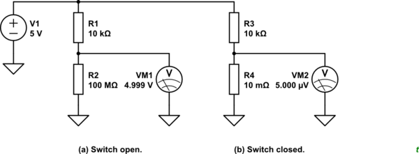
The resistor and the switch contact resistance (10 mΩ, say, when closed and 100 MΩ when open) form a potential divider.

schematic

simulate this circuit

Figure 4. The results of the potential divider caused by the pull-up resistor and switch resistance.

\$\endgroup\$
13
  • \$\begingroup\$ I'm just saying how I think it is easiest to understand it. And pointing out that the meme "people usually have a hard time understanding the pull up resistor concept" is pretty common. If you look at introductory material to it. So, that it is actually very easy, well, for some reason, people still have a hard time getting it. I explained how I found it was most easily explained, and from that PoV I agree it is very easy. \$\endgroup\$ Commented Sep 16, 2021 at 13:04
  • \$\begingroup\$ As someone learning the concept, figure d) in your schematics does achieve everything people emphasize that the pull up resistor is used for. But, it short circuits at logic low. So, as a noob, it is much easier for me to be taught that the figure d circuit is what resolves the floating issue, but, that it requires a resistor to avoid short circuit at logic low. \$\endgroup\$ Commented Sep 16, 2021 at 13:06
  • \$\begingroup\$ Your last paragraph, "This will happen every time SW4 is opened in Figure 2c above. R2 pulls the input high.", well figure d) does that too. But it has the issue that it short circuits at logic low voltage. That was my point, the resistor R2 does not "pull input high", the design choice to connect V+ directly to Buf without a switch in between does, figure d). \$\endgroup\$ Commented Sep 16, 2021 at 13:08
  • 1
    \$\begingroup\$ No, you are thinking backwards. The switch is there for logic low. When the switch is open the resistor prevents an undefined logic level persisting by pulling (weakly relative to the switch) the input up. Again, we would never use a switch on an input tied directly to V+ so your situation never arises. \$\endgroup\$
    – Transistor
    Commented Sep 16, 2021 at 18:55
  • 2
    \$\begingroup\$ OK. I don't think there is any point discussing this further. \$\endgroup\$
    – Transistor
    Commented Sep 16, 2021 at 19:07
1
\$\begingroup\$

I agree that the use of the terms "pull-up" and "pull-down" can be, and are often misused, or misleading. What I say here just my opinion.

I think the use of the term "pull-up" or "pull-down" is appropriate to use when some signal is intended to change, but which could, under certain circumstances float. In other words, if at some point in time, all the devices that could potentially impose a potential on that node are not doing so, then the input is floating, and if such a condition is undesirable, we must pull up, or pull down.

Examples of this could be:

  • A simple switch used to connect an input to ground, thereby imposing a logic zero at the input. When the switch is open, however, the input would be floating.

  • An I²C bus, where many open collector/drain outputs could potentially impose a logic zero onto the same line, but very often none of them do, leaving the node floating.

  • Two or more diodes used to "wire-OR" logic levels from a set of voltage sources onto some common output node. If no source is high, then that output is floating.

  • You have several three-state logic outputs driving the same node, and that node will be floating when none of them are enabled. This leaves any MOSFET gates connected to that node vulnerable to pick-up, and ESD.

These situations all have one thing in common - the signal is expected to change value. It is not intended to be permanently and immovably held at some fixed potential. It is intended to vary, under the influence of other elements, but in the absence of any element actively "imposing its will", there exists an undesirable floating state, the solution to which is a gentle pull up or down in potential with a resistor.

How gentle? Well, as the video suggests, exactly as gentle as the application calls for. To solve the last problem, a "weak" 1MΩ pull-down resistor to ground is all that's needed. Ill talk more about this later.

Now contrast this with other reasons for floating inputs, and how we address them:

  • You have a 4-input AND gate, but you only need 3 of those inputs. The other one is unused, but it must be "held permanently high" for the AND gate to function as a 3-input AND gate.

  • You have a CMOS logic IC with 4 gates, but you only use 3 of them. All inputs of the unused gate must be held either permanently high or permanently low to prevent switching, and excessive current draw.

  • I've run out of examples. I'll put some more here when I am reminded of them.

In these situations, there may be a wire or resistor in place to hold the signal's potential at some value, but I do not think the term "pull-up" or "pull-down" is approriate in these cases, because it was never intended for the signal to have any other value. That's why I deliberately avoided using it in my descriptions above. I prefer the term "to hold at 0V" or "to be held high".

All that said, if somebody does say something like "I pull-up the unused AND input with a wire to Vcc", I know what they mean, and though I may not agree with their use of the term "pull-up", it's not egregious, or strictly wrong.

However, if somebody said "I hold the I²C clock high with a resistor", my ears would hurt.

It's really just pendantry on my part, and I shall accuse you here of a similar crime. You used the term "wasting current", and my eyes watered a bit. You draw current, and you waste energy. The thing is, I know what you meant, and that's all that matters.

How do you choose the resistance? You choose it based on the following considerations:

  • How much energy can you afford to waste in the resistor? Is this a super-low power, high efficiency design?

  • What is the resistor fighting against, in its tug-of-war with all the other things that want to "pull" the voltage in the opposite direction? Does it need to pull hard, or gently in order to coerce a floating input to some unambiguous potential?

  • How much interference do you expect to be present, which might be able to overcome the resistor's ability to maintain an acceptably constant voltage at the input?

  • When the signal suddenly floats (because the other elements suddenly stopped pulling down), how important is the rate at which the resistor pulls up the potential? Does the input require the transition to be rapid and emphatic, or can the "pull up" be a gentle, sedate affair?

If the most important consideration is power, then you want the largest resistor possible. If noise immunity is critical, you need low resistance. If you need fast signal slew, then low resistance is better. If the input you are driving is high impedance, then you don't need to pull hard, and pull-up resistance can be large. In the end, the resistance you choose will be a compromise of all these things.

\$\endgroup\$
1
\$\begingroup\$

Let’s be clear we’re talking about a signal pull-up here, as opposed to an output type that requires a pull-up to work (like NMOS, as you asked in your earlier question Depletion transistor in 6502 nand gate)

The thing you should try to understand is the term ‘impedance’. A signal can be driven high, driven low, or not driven at all (sometimes called ‘floating’.) The first two cases are ‘low impedance’, while the latter is ‘high impedance’. These are the three states of a signal.

As you may know, a MOS transistor insulated gate has nearly infinite resistance and only a tiny capacitance. By itself, it is also high impedance.

The pull-up (or pull-down) provides a medium-impedance DC path to tie a high-impedance node to a known state when there is no driver. It sets the ‘default’ state. Without this default, an un-tied, undriven signal will cause the things connected to it to behave unpredictably: it will float to an in-between level, pick up noise or even oscillate, which the receiving devices could falsely interpret as a valid logic level.

This untied-input concern mostly applies to CMOS and NMOS, which have very high input impedance. But bipolar logic can be vulnerable too, noise coupling to untied inputs being the main issue with TTL.

On the other hand, if there is always a driver, then the tie-off isn’t necessary. A CMOS driver will put the signal in either a solid (low-impedance) ‘1’ or ‘0’.

Do pull resistors use power? You bet, but only when the signal is driven to the opposite state (pull-up driven low for example.) When the signal is undriven, no power is wasted.

Where do we see pull-ups being used? Mostly with shared signals, like 3-state buses and wired-OR open-collector logic. I2C Bus is an example of a shared, open-collector bus that uses a pull-up to define logic high.

Why is the ‘pull-up’ more popular than ‘pull-down’? Tying a signal high has better noise margin with certain types of logic (TTL, HCT, AHCT) that use TTL thresholds. For CMOS it doesn’t matter, pull-up or pull-down work equally well. Nonetheless designers preferentially choose pull-up out of habit.

Finally, another way to tie off a high-impedance signal is to use a circuit called a ‘weak keeper’ latch. The line retains the last state it was driven to. This uses less power than a pull resistor.

\$\endgroup\$
-3
\$\begingroup\$

Having understood what I missed, I’ll answer this question, in the way I think it explains what I asked. This could benefit anyone else who had the same question.

I assumed the pull up works by creating a “preferred path” for noise so that it bypasses the base. This assumption is false.

How they actually work, is by connecting the base to a negative voltage. In schematics, this is shown as “ground”. I’ll skip the “ground” concept in my explanation.

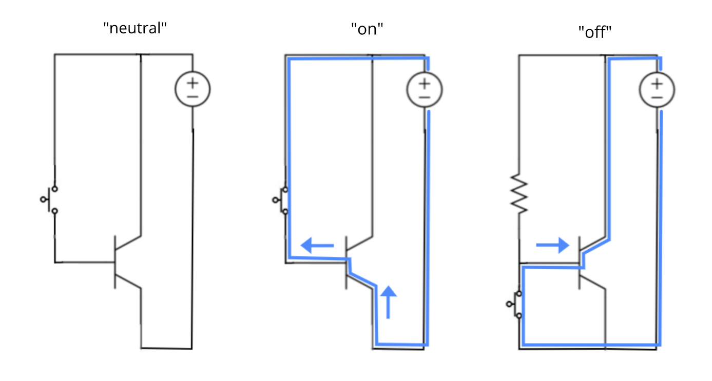
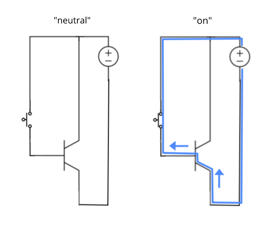
Transistors can be in three states. They can be in “neutral”, and block electricity. They can be in “off”, and block it even more. And they can be “on”, and conduct electricity.

Transistors are turned “on” by a positive voltage at the base. And, “off” by a negative voltage at the base. And, they are in "neutral" with no voltage at the base.

enter image description here

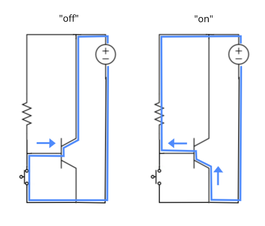
It would be easiest to use transistors with just the “neutral” and “on” modes, since that is enough for them to either conduct or not conduct electricity. But, the wires in the circuit act as antennas and currents can be induced in them from electromagnetic “noise”, and it might be enough to turn the transistor “on”.

enter image description here

By adding the “off” mode (replacing "neutral" with it), any “noise” is outcompeted when the transistor is “off” (and already was when it is “on”. )

enter image description here

\$\endgroup\$
3
  • \$\begingroup\$ Have no interest in what you do normally or not. My impression is that reversing polarity at base will turn it more "off" than in disconnected state. I can appeal to some references for that, but, it is easier to be able to have a conversation. Here is one for MOSFET, electronics.stackexchange.com/questions/242924/…, stating reverse biasing when negative voltage applied to base. I have another user on this forum, claiming a meme I suggested is wrong, while three other users here claim it is right. So, I'll trust my judgement, based on data I can access. \$\endgroup\$ Commented Sep 25, 2021 at 14:23
  • \$\begingroup\$ Yes just because anyone thinks anything, does not make it true. Because people and the human condition is not a perfect reasoner. To provide some more references, socially (that are imperfect as well yes, just like yourself), I was polite enough to give you ability to look at some users here stating that negative voltage at gate reverse biases and turns off (more so than disconnected state) transistor, electronics.stackexchange.com/questions/242924/…. I have another user claiming something is false as well, while a couple of others claim it is true. Etc. \$\endgroup\$ Commented Sep 25, 2021 at 15:32
  • \$\begingroup\$ For the record, my replies were to a user who deleted their comments. Without saying who that was, here were the comments, "Normally, I don't do this. But you are wrong on so many levels. " "Just because you think it, does not make it true. And your fixation on pull up resistors has skewed your understanding on how transistors (BJT or MOSFET) work. " I gave polite references to content that corroborates the "off" state from reverse polarity, and, my answer is aimed at being simple enough for new people. I think my understanding is right, I'm pretty good in different fields & know how to think. \$\endgroup\$ Commented Sep 25, 2021 at 15:55

Your Answer

By clicking “Post Your Answer”, you agree to our terms of service and acknowledge you have read our privacy policy.

Not the answer you're looking for? Browse other questions tagged or ask your own question.