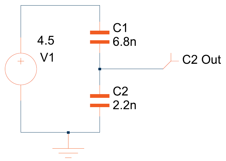
Simulators create a matrix of simultaneous equations, and then solve them. If a node has no DC continuity, as C2out doesn't, then at DC the matrix is going to have one fewer constraints than unknowns, which makes the system unsolvable, or in matrix algebra terms, a singular matrix. This is quite physical, you can imagine that output node having a DC voltage of 2 V, or 10 V, both are possible.
You need some DC continuity from C2out to anywhere with a defined voltage, GND is often the choice. A large resistor, 10 M or so, will do, as long as the time constants are large enough not to disturb your interpretation of the results. Larger resistors can be used, but eventually you'll run into numerical dynamic range problems if you try to use one too large.
That will of course define the DC output voltage. That's quite physical as well. If you build that circuit, the DC value of C2out will drift to whatever node it has any leakage path to. If you measure that voltage with a multimeter, you'll find the leakage current into the device makes it reach zero soon enough.
You can define 'initial conditions' on capacitor voltages in most simulators. You can also make that voltage source 0 before the start of the simulation, and jump to 4.5 V once the simulation starts, if you want to see the effect of steps into such a divider.
--- EDIT ---
If, as you say, you're trying to measure the DC voltage, it won't work, even with a 15 GΩ buffer following. Its leakage, and board surface leakage, will quickly render the voltage on the mid point meaningless. CVDs, capacitive voltage dividers, only work for AC, not for DC. In that sense, the simulator is warning you of the exact truth, that the output is undefined.
The LearningAboutElectronics link you've found is doing you a disservice by failing to warn about this.
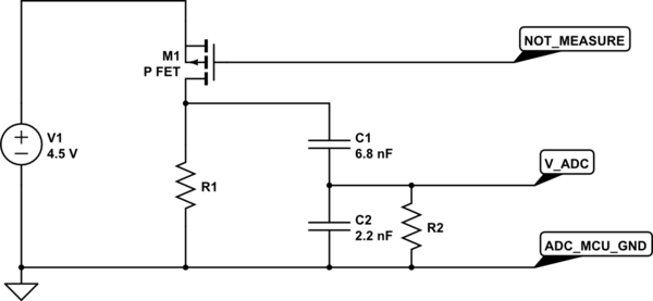
There is a complicated way of using a CVD to measure battery voltage with low current.

simulate this circuit – Schematic created using CircuitLab
R1 and R2 ensure that both capacitors are fully discharged while the circuit is idle. When you want to take a battery measurement, pull NOT_MEASURE low, the PFET turns on and applies a step of the battery voltage to the CVD. The V_ADC node rises to the value you expect, and then immediately starts an RC decay down to 0 V due to R2. If you read the voltage on the ADC quickly enough, the resulting error will be small. Then send NOT_MEASURE high again, and the capacitor voltages settle down to 0 V for the next cycle.
R1 and R2 need to be small enough to reset the capacitor voltages before the next cycle. R1 needs to be large enough for minimal current consumption during measure, and R2 large enough to minimise the RC sag reading error during measure.
There is a potential problem that if the software allows a very long measurement, due to a crash for instance, charging C1 fully and discharging C2, then when the circuit goes idle, R1 will take V_ADC negative, which might be a problem depending on the ADC. The current is limited by R1, so the ADC should survive.
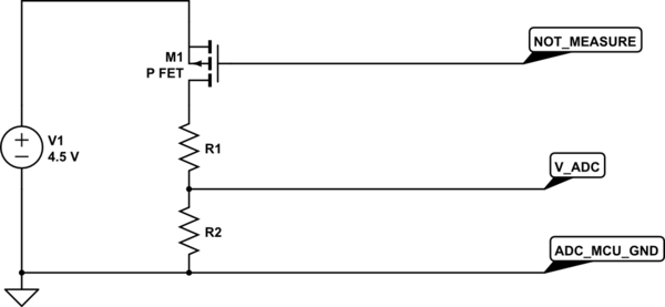
What people generally tend to do for low current consumption is a switched measurement circuit similar to what's shown for the CVD, but with modest value resistors which can drive the ADC without a buffer amplifier. The current used will be relatively high during the measurement period, but with a short measurement and a low reading rate, the average current consumption will be small.

simulate this circuit


