1
\$\begingroup\$

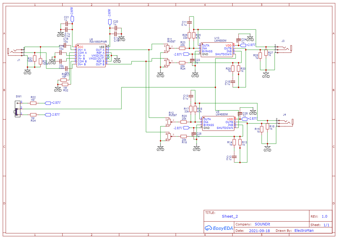
Here's my idea of a portable headphone amplifier.

A line receiver INA1650 (instrumentation amplifier with all its benefits) that feed two LM4880 that drive the headphones (with separate volume control.)

The power supply would be a split +-2.85V, just below the maximum 6V allowed by the LM4880.

Now my doubts are:

  1. The INA1650 requires a minimum of +-2.25V to work, would 2.85V be too little to make it work well?
  2. According to the typical application 8.2.5 (INA1650) it has on the tip and ring traces a 100K resistor to ground. Are they really needed? Wouldn't the 500k resistors at the input pins in the chip itself be enough?
  3. Is the Cb capacitor still needed at the bypass pin when using the LM4880 with a split supply? 4 I need the total current draw in order to know if the voltage regulator I choose is good enough for the circuit. For each LM4880 ~0.09 A (250mW @ 5.7V per channel) and about 100mA for the INA. Would that be around 300mA for the whole circuit?

EDIT: in order to save battery life, when not in use, I need to be able to switch everything off (i.e. quiescent). Instead of using the on/off switch for the LM4880s, I thought about disabling the regulator's enable pins with a DPST switch. That should take care of everything. Would that be the best solution? Any idea?

enter image description here

\$\endgroup\$
5
  • 1
    \$\begingroup\$ Pretty gutsy trying to run the LM4880 off a bipolar supply. I don’t see any overt flaws other than the SHUTDOWN input needs to select between +2.85 and -2.85, not ground. (1) If 2.25V is spec then 2.85V should be fine. (2) Your pot to ground an LM44880 input resistance should be fine – don’t need extra pulldowns. (3) I think you’re right – can just ground BYPASS. (4) I’d bump up regulator to 500mA – headphones can generate large current spikes that can drag down weak supplies. \$\endgroup\$
    – td127
    Commented Sep 27, 2021 at 18:00
  • \$\begingroup\$ I'll add: you almost can't put too much bypass capacity, especially when working with analog (or high speed digital). The two resistors are explained in the application, they are for discharging the AC coupling capacitors \$\endgroup\$ Commented Sep 27, 2021 at 20:25
  • \$\begingroup\$ Thanks! Just one question: why the shutdown input needs to switch between + and - 2.85V? \$\endgroup\$
    – Status Re
    Commented Sep 29, 2021 at 4:12
  • \$\begingroup\$ The LM4480’s voltage rails are its “GND” pin and “VDD” pins which you’ve wired to -2.85V and +2.85V so those are the voltage levels that the LM4480 interprets as low and high. Circuit ground of 0V is just an intermediate voltage that should be avoided for a logic level input like the SHUTDOWN pin. The datasheet (pg 10) says the trigger point is “typically half supply” which is about 0V in your case so need to fully “switch between ground and the supply”, but ‘ground’ as far as the LM4480 is concerned is -2.85V. Also, put big (electrolytic) caps on rails to help with headphone transients. \$\endgroup\$
    – td127
    Commented Sep 29, 2021 at 17:03
  • \$\begingroup\$ Thanks, I edited the schematic \$\endgroup\$
    – Status Re
    Commented Oct 1, 2021 at 18:52

0

Your Answer

By clicking “Post Your Answer”, you agree to our terms of service and acknowledge you have read our privacy policy.