1
\$\begingroup\$

enter image description here

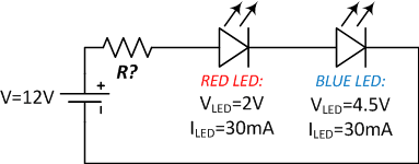
This is a circuit from a tutorial I found on the internet, which is apparently correct.

R equals 183.3 ohms as the LED requires 30mA. So the voltage drop accross the R is 5.5 V.

I browsed quite a lot about Ohm's law but I'm afraid it still does not click.

Here is how I read this circuit:

The power supply generates 12 V DC and encounters the resistor R.

The resistor is 183.3 ohms because the red LED needs 30mA.

The voltage available "after" the R and at the door of the red LED is 6.5V, since the voltage drop across R is 5.5V.

How come the red LED does not burn?

According to my dubious logic, this would also mean that LEDs with higher voltage drops have to be "at the left" of the circuit. From left to right, in a row: highest voltage LED to lowest voltage LED.

Don't components each drop a bit of voltage, one after the other, so that in the ends 0 V come back to the power supply? Don't component each "consume" a bit of current?

Can you spot and explain what is wrong in my way of interpreting a circuit?

\$\endgroup\$
3
  • 1
    \$\begingroup\$ The key thing is that current is the flow of electrons; they are pushed out of the negative terminal of the battery and through the LEDs and resistor and eventually back into the positive terminal of the battery. So the current has to be the same in each component. The components don’t ‘know’ what order they are in, just that something is pushing electrons through them, and each component resists the flow according to its own characteristics. \$\endgroup\$
    – Frog
    Commented Oct 2, 2021 at 0:46
  • \$\begingroup\$ When you connect the battery, there is a very tiny moment in time (on the order of a nanosecond or so) while charges re-arrange themselves on the surfaces of the conductors. Afterwards, that equilibrium state has been satisfied and the currents will arrange themselves according to the new fields present throughout the circuit. If you want to see these surface charges in action, watch this physics demonstration. \$\endgroup\$
    – jonk
    Commented Oct 2, 2021 at 4:13
  • \$\begingroup\$ On the order of a nanosecond if the circuit is on the order of one foot around. Wrap the circuit around the periphery of a football field and it'll be on the order of a microsecond. Wrap the circuit around the periphery of a small city and (assuming you don't get arrested before you're done) it'll be on the order of a millisecond. \$\endgroup\$
    – TimWescott
    Commented Oct 2, 2021 at 14:07

4 Answers 4

3
\$\begingroup\$

Resistance isn't "encountered" in the sense that you encounter a road block as you travel. Resistance is established instantly everywhere in the circuit, and determines as a whole what current flows. The current entering a chain of resistors or diodes is the same as the current leaving it, and it doesn't get slower as it encounters each resistance.

Current gets reduced everywhere in the path, by the total resistance everywhere along that path. In this sense resistance is like an obstruction in the road, but you have to understand that all traffic everywhere along the road is slowed, not just in the vicinity of the blockage. You could add another blockage a mile further down the road, and you affect the speed of traffic everywhere along the road.

Voltage doesn't "travel" anywhere, it doesn't "arrive" at places, it doesn't go through things. Voltage is something that exists at a point (or more precisely, a voltage difference exists between two points). Voltage is established instantly at every point in a circuit, and while voltage does depend on the obstacles along a current path, it must not be considered a "travelling" thing.

Putting all this together, you can understand that it doesn't matter what order the resistances or diodes appear in a path, the current will not change because you swapped the locations of things. The voltage difference across those things doesn't change because you swapped their positions. The total resistance to current along that path doesn't change depending on the order of the things in it.

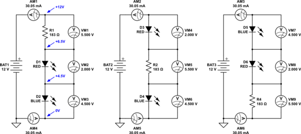
So, it should be no surprise that the following three circuits all do exactly the same thing, develop the same voltages across the various components, and have the same current flowing in every case:
schematic

simulate this circuit – Schematic created using CircuitLab

Every blue LED has 4.5V across it, every red LED has 2.0V across it, and every resistor has 5.5V across it. In every case, the current leaving the battery at the top, and entering the chain, is the same as the current leaving the chain at the bottom and returning to the battery.

Do not confuse voltages across things with absolute voltages quoted anywhere. I've done this for the first circuit, where the labels in blue are absolute potentials, not potential differences. Starting at the bottom, I've declared the lowest node to have 0V, which you can also tell by the ground symbol at that same node.

As you cross each component the voltage changes by an amount equal to the voltage difference across the component you traverse. Jumping from the 0V node across D2, the voltage rises by 4.5V, so the voltage at that node is 0V + 4.5V = 4.5V. Jump across D1, and the voltage rises a further 2V, so at the top of D2 we can say the voltage is 4.5V + 2.0V = 6.5V. The last jump across R1 incurs a rise of another 5.5V, so the top node must be 6.5V + 5.5V = 12V. I hope it's completely clear, the contextual difference between declaring a voltage "at" some point, and a voltage difference that exists "across" or "between" two points.

The correct model

Not one of the trillions upon trillions of charges making the journey around is being slowed down because it's passing through something difficult to traverse. There's nothing happening in that loop that that says "first come first serve". Every charge is slowed everywhere by all the obstacles, simultaneously. Every voltage is established instantly, depending on the component, not depending on who's first in line.

If you have any ideas in your head that do not fit with this model, you must drop those ideas immediately, right now, because they are bad things taught by people who either don't understand themselves, or who are trying to explain things to a five year old.

Note: I feel I should point out that when you start dealing with really high frequencies, things get way more complex, and some phenomena related to these "bad" ideas might actually become significant, but not in these early stages of learning.

For now, learn these three things, and understand them like your life depends on it:

  1. Ohm's Law
  2. Kirchhoff's Current Law
  3. Kirchhoff's Voltage Law

They should be a lot easier to deal with once you've dispensed with all the rotten models which don't fit or work. If I haven't made this clear yet, remember that all voltages and all currents are conditions that are established everywhere, simultaneously. All the equations relating them are all true at the same time, and must be solved simultaneously using all the resistances and other impedances present everywhere.

Your example

Let's analyse your circuit using those 3 laws.

Kirchhoff's Current Law tells us that the same current is passing at every place in the loop, through each component. We want that current to be:

$$ I = I_{BATT} = I_{R1} = I_{D1} = I_{D2} = 30mA $$

We know the voltage across the diodes, because we looked it up in the datasheet:

$$ V_{D1} = 2V $$ $$ V_{D2} = 4.5V $$

We know the battery voltage:

$$ V_{BATT} = 12V $$

We don't know the resistance yet, but we can apply Ohm's law:

$$ V_{R1} = I \times R = 30mA \times R_1 $$

Kirchhoff's Voltage Law applied here tells us that all the voltages across R1, D1 and D2 must add up to the battery voltage (we saw this when we walked up the chain to establish absolute voltages earlier). I'll write different versions of the same equation to demonstrate that we don't care about the order:

$$\begin{aligned} V_{R1} + V_{D1} + V_{D2} &= V_{BATT} \newline V_{D1} + V_{R1} + V_{D2} &= V_{BATT} \newline V_{D2} - V_{BATT} + V_{R1} &= -V_{D1} \end{aligned}$$

Putting everything we know into that equation:

$$ 30mA \times R_1 + 2V + 4.5V = 12V $$

Now you have everything you need to solve for R1. The real takeaway from all this is that at no point did I ever refer to the order of the components, because these are simultaneous equations, not "solve one by one in the order they appear in the loop" equations.

The only reason you might need to consider the component order, is when you need to find the absolute voltage somewhere, as we did when we "walked" up the chain adding the voltages across each component as we went. Think about that - that exercise was a (somewhat trivial and contrived, but still valid) application of Kirchhoff's Voltage Law. We saw that the voltage across two or more components must be the sum of the individual voltages across them.

\$\endgroup\$
5
\$\begingroup\$

Kirchhoff's Voltage Law tells us that the sum of all the voltage drops in a series circuit has to be the same as the input voltage. And so it applies here, as all the components are in series.

Let's add them up then:

  • R? = we don't know that yet.
  • Red LED: 2V
  • Blue LED: 4.5V

And so how to we find the voltage drop for R? We know that the supply is 12V, so with a bit of re-arranging we get:

  • R? voltage + 2V Red LED + 4.5V Blue LED = 12V, so
  • 12V - 2V - 4.5V = 5.5V across the resistor R?.

We can then also calculate the voltage at each point in the circuit:

  • Supply to R? (Red LED anode) = 12V - 5.5V = 6.5V
  • Red LED cathode to Blue LED anode: 12V - 5.5V - 2V = 4.5V
  • Blue LED cathode: 12V - 5.5V - 2V - 4.5V = 0V, just like we expect.

Ok, so how about that resistor? We also know that Kirchhoff's Current Law says that for a single closed loop circuit like this, all the currents are equal. They state the current flowing is 30mA. This allows us to find the value for R?, using Ohm's Law as follows:

  • R? = V/I = R? Value, so
  • R? = 5.5V / 30mA = 183.33 ohms

So why doesn't the Red LED burn? Because the total current across both LEDs in series is limited by the IR drop across the resistor, while the IR drop across the two LEDs is constant (sorta.) Nevertheless, the current through all 3 elements is the same, no current is 'lost'.

\$\endgroup\$
5
\$\begingroup\$

I think this is the underlying problem:

The voltage available "after" the R and at the door of the red LED is 6.5V, since the voltage drop across R is 5.5V.

How come the red LED does not burn?

According to my dubious logic, this would also mean that LEDs with higher voltage drops have to be "at the left" of the circuit. From left to right, in a row: highest voltage LED to lowest voltage LED

The red LED would indeed burn if one terminal was at 6.5V and its other terminal was at 0V, but that's not going to happen in this circuit. The red LED in this circuit has one terminal at 6.5V and its other terminal at 4.5V, however the red LED itself does not know where ground is -- it only sees the difference between its two terminals, it doesn't make any difference to the LED whether its Vf is (6.5V - 4.5V) = 2V or whether it is (99V-97V)=2V or (1V minus -1V)=2V, the LED itself has no connection to ground.

Same with the blue LED. The voltage across the LED is what matters, the LED itself doesn't know where ground is. So it doesn't make any meaningful difference whether the red LED is "first" or not. It would only make a difference if those terminals connected to something else.

There really isn't a "first" component anyway, it's not as though "electrons" are being squeezed out of one end of the battery, and losing voltage as they hit various components. It's sort of like that, but not quite. There are electrons drifting around, and there are waves of energy conveyed by the electrons, but it's not like one electron is screaming through the wires doing all the work by itself. It's more like if you imagine a sports arena full of fans, and suddenly someone starts "the wave" where each person in the stadium stands up when the person next to them stands up, and it looks like an ocean wave travelling through the stands... it goes around the whole stadium back to the start, and the wave itself travels much faster than any of the people that it is "made of". Electric current is like that wave, and the people in the stands are like the electrons.

There is no such thing as absolute voltage, we always designate what point in the circuit we're calling 0 volts or ground. If you designate the 0V point as being the point between the two LEDs, all of the math still works out the same, with the only thing different in the analysis being that the voltages are "shifted" in the model -- but the real circuit still works the same way.

Sometimes people try to understand electricity by imagining that it works like something else, like gears and pulleys, or like water in a pipe, or toothpaste being squeezed out of a tube, or like some other mechanical system -- but these models never quite work exactly right, for example the water metaphor suggests voltage is similar to water pressure, and current is like the flow of that water. But water pressure has an absolute value, while voltage (electric field) does not. And electrons don't leak out onto the floor if the wires are left unconnected. So these metaphors lead to this kind of confusion.

A common misconception about Ohm's law is that it applies everywhere to everything; but it only applies to resistive elements. Ohm's law doesn't apply to ideal voltage sources, and it doesn't apply to diodes. Diodes (including LEDs) are kind of hard to model, but for LEDs we can assume the given operating point of "Vf voltage across the LED when there is If current flowing through the LED". The only element in this circuit where you can use Ohm's law is the one resistor, the voltage across the resistor is determined by algebraic sum of the voltages around the rest of the loop (12V - 4.5V - 2V = 5.5V), and the current is determined by the mesh current (which is the same for all components because they're connected in series, 30mA); and applying Ohm's law gives the resistance 5.5V / 30mA ~= 180 ohms (nearest real resistor component value).

\$\endgroup\$
1
  • \$\begingroup\$ Ok so it is the potential difference between the leads that matters for the LED, not the absolute value of the voltage it sees at its entrance. Your first paragraph is what I needed the most I guess. \$\endgroup\$
    – Musa
    Commented Oct 2, 2021 at 7:34
0
\$\begingroup\$

I think you're confusing the circuit with one where the two LEDs are in parallel. If that were true, then the red LED would indeed burn.

Since the two are in series, their voltages at the same current add. 4.5 plus 2 gives 6.5, and 12 minus 6.5 is 5.5, the voltage across the resistor.

\$\endgroup\$

Your Answer

By clicking “Post Your Answer”, you agree to our terms of service and acknowledge you have read our privacy policy.

Not the answer you're looking for? Browse other questions tagged or ask your own question.