0
\$\begingroup\$

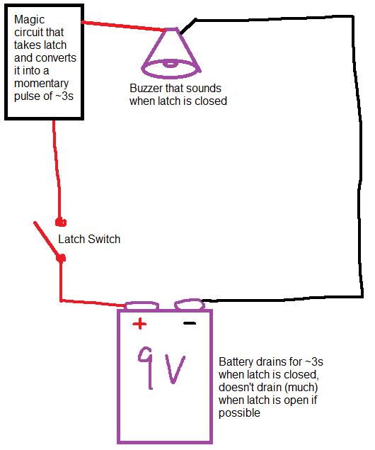
I'm trying to get a latch switch to send a pulse for around 3 seconds or so. The pulse doesn't need to be pretty or precise. The circuit will be used to sound a buzzer when the switch is flipped on. It shouldn't sound when the switch is released, as supposedly no current will be flowing from a 9V battery I'm strapping to it.

I know you can kind of accomplish something like this with a Schmitt trigger gate, maybe. It's been over 5 years since my electrical engineering course and I'm a bit stumped. I'd use a 555 IC if that'd work with a latch switch, but I'm not sure how to get that to work as I think it requires a momentary pulse from a button or something.

Here is a criminally bad diagram shows what I'm trying to do.

A sin against circuit diagrams everywhere

Any help is greatly appreciated.

\$\endgroup\$
3
  • \$\begingroup\$ This may help - electronics.stackexchange.com/questions/338336/… \$\endgroup\$
    – HandyHowie
    Commented Oct 3, 2021 at 8:50
  • \$\begingroup\$ Can you run a wire to the negative terminal? If yes, you can use a monostable multivibrator (555 is one). \$\endgroup\$
    – winny
    Commented Oct 4, 2021 at 8:19
  • \$\begingroup\$ @winny Yes, I probably could. Could you explain how I could use a 555 IC in that case? \$\endgroup\$ Commented Oct 5, 2021 at 18:16

2 Answers 2

1
\$\begingroup\$

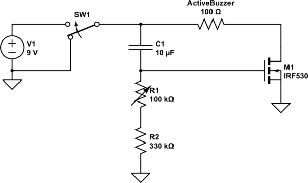
If you can substitute for the SPST switch you show in your drawing, a SPDT switch, with one contact connected to positive, and the other to negative, it will almost certainly make your solution simpler.

Here is a possible solution for you. The timing of the circuit is not very accurate. If you need accuracy, let me know, and I will give you a more complex circuit. Instead, this circuit uses a variable resistor to adjust the duration of the alarm.

There is a resistor symbol in the schematic labeled ActiveBuzzer. As you may have guessed, it represents the active buzzer. An active buzzer will make a sound simply by applying a voltage. Some buzzers are passive, and require an external oscillator in order to produce a sound. You can ignore the resistance value. I simply used an arbitrary value in order to simulate the circuit.

The timing of the circuit, as I mentioned, is not very accurate. It depends upon both the state of battery charge and the threshold voltage of the mosfet. Threshold voltages of mosfets vary widely. You can, and perhaps in some cases need to, change the values of R2 and C1. The larger either is, the longer duration the alarm.

The circuit draws almost no current except when the buzzer is active.

If you cannot substitute a SPDT switch for the SPST switch, the circuit will be necessarily more complex.

schematic

simulate this circuit – Schematic created using CircuitLab

\$\endgroup\$
6
  • \$\begingroup\$ Can you explain where ground would go to in this circuit? Would it just circle back to the negative terminal in the battery? I could potentially replace the switch as you suggest. \$\endgroup\$ Commented Oct 4, 2021 at 5:11
  • \$\begingroup\$ Yes. All the ground symbols in the schematic are connected together (which in this case means they are all connected to the negative terminal of the battery. Schematic grounds are not necessarily connected to the physical earth. Since you are using a battery, and not mains power, there is no reason to connect them to physical earth. \$\endgroup\$ Commented Oct 4, 2021 at 6:01
  • \$\begingroup\$ I will put a prototype together this week and update this question with the results. Thanks for your assistance. \$\endgroup\$ Commented Oct 5, 2021 at 1:25
  • \$\begingroup\$ Hey, I can't get this circuit to function. Using an LED as an indicator for the circuit, and a 33k ohm resistor in place of the potentiometer, the LED just stays on indefinitely when the SPDT switch is connected to the positive terminal, and off indefinitely when connected to the negative. I've tried it with the resistances/capacitor provided, and also reduced the capacitor/resistor to see if the pulse was just too long. Any ideas on what I might have done wrong? The northern mosfet terminal is the Drain, The western terminal is the Gate, and the southern is the Source in terms of the diagram? \$\endgroup\$ Commented Oct 9, 2021 at 4:46
  • \$\begingroup\$ Yes, the northern terminal is drain, western gate and southern is source. Can you show me what you did? Are you sure you connected the right MOSFET pins? Many data sheets show pun diagrams from underneath the transistor. Does your circuit work when you use an active buzzer? \$\endgroup\$ Commented Oct 9, 2021 at 5:10
1
\$\begingroup\$

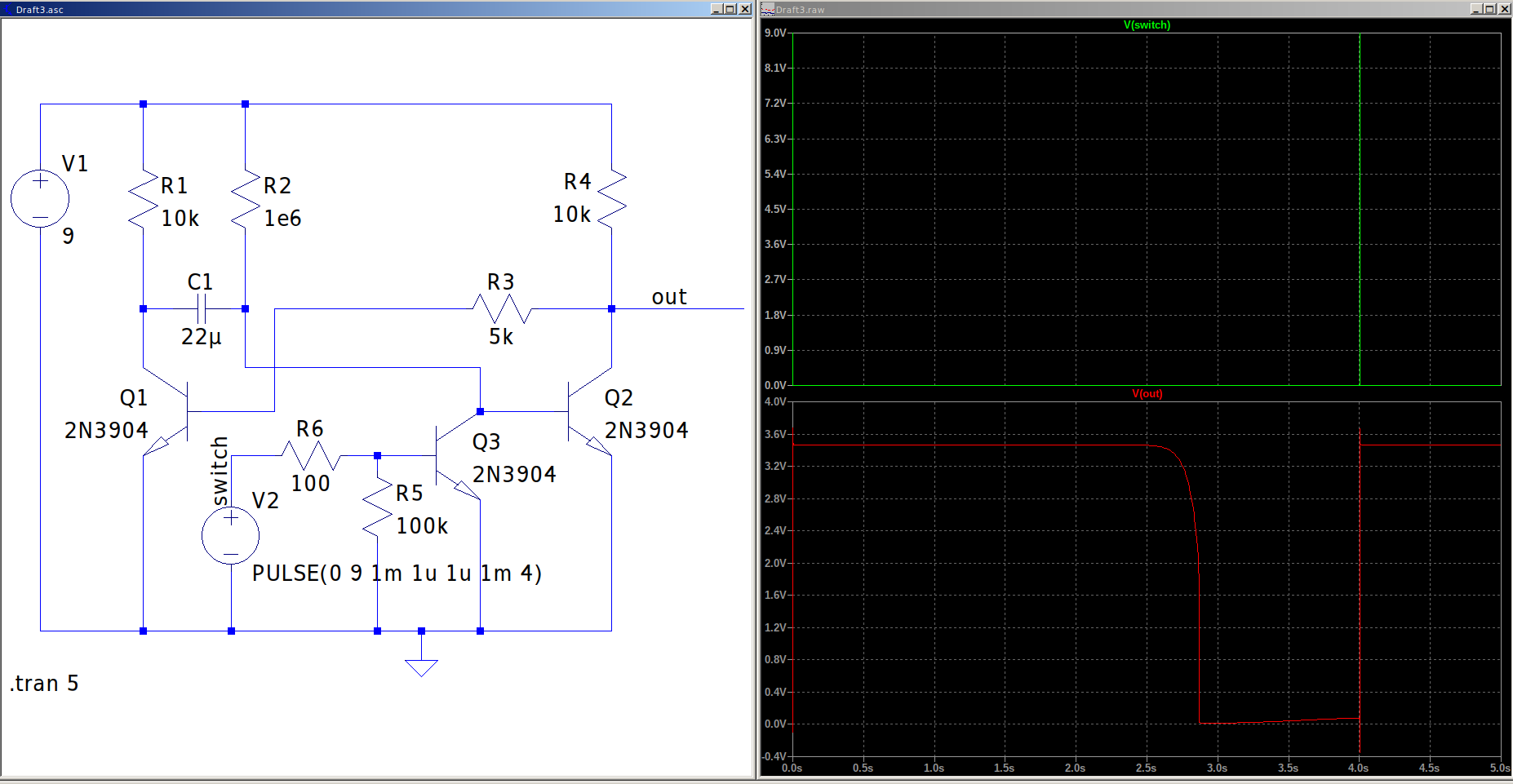
You are probably looking for a monostable circuit, which can either be accomplished with a 555 ic or with with a few transistors. Here is a small simulation using some bipolar devices.

image_1

The trigger input was replaced with an inverter in order to latch on the positive edge (switch on).

\$\endgroup\$

Your Answer

By clicking “Post Your Answer”, you agree to our terms of service and acknowledge you have read our privacy policy.

Not the answer you're looking for? Browse other questions tagged or ask your own question.