0
\$\begingroup\$

enter image description here

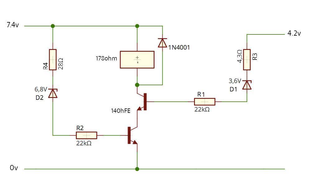
As seen in the schematic, I need to control a relay using two voltage sources.

The relay goes off when source Nr.1 (4.2V) is less than 3.6V AND when source Nr.2 (7.4V) is less than 6.8V, by the effect of the Zener diodes D1 and D2. The value of the desired cutoff voltage of the Zener diodes has been reduced in 0.7V, in consideration of the transistors Vbe drop.

The Zener diodes resistors (R3 and R4) were calculated on the basis of their maximum power (500mW), using the formula (Vs-Vz)/Iz. Then a series resistor of 22k biases the transistors, whose hFE is 140 (BC549A.) The formula used was (Vs-0.7)hFE divided by the relay current.

Is this well calculated? It is the first time I design a circuit and I'm not sure if the application of the formulas for resistor values is correct and if the transistor base resistors (R1 and R2) will interact badly with the Zener resistors (R3 and R4.)

Any suggestions or different approaches to it will be very much welcomed.

(This question follows indirectly another recent post of mine.)

\$\endgroup\$
2
  • \$\begingroup\$ For your Base drive \$Ib\$, since you are using them as switches, you will want to overdrive them by 10-20% to make sure that Vce is small, and they are not dissipating much power. \$\endgroup\$
    – Aaron
    Commented Oct 5, 2021 at 19:22
  • \$\begingroup\$ The values of R3 and R4 are insignificant compared to R1 and R2, so they can be removed - they will have no effect on hte operation of the circuit. \$\endgroup\$ Commented Oct 31 at 15:48

1 Answer 1

1
\$\begingroup\$

First of all you dont expect you make a precise cut with simple zener circuit. The second you must know if you want AND or OR logic.

If you do an OR logic you can reduce design to one transistor (both logic to one base). For AND it is a good approach (two transistors in series).

A third relay should have a stable supply voltage (not floated).

A 4-th 22k cant open 40mA for supplying relay with considering Beta=140, you would need about 14V at top of R4.

A 5-th using two resistors in series makes no sense.

\$\endgroup\$
1
  • \$\begingroup\$ Thank you for your reply Michal. This is definitely intended to have an AND logic, by mistake I wrote AND/OR in the original question which I corrected. Why are you assuming that there will be a 3rd, 4th and 5th relay? The circuit is only intended for one relay and I need to know if my values are precise enough. But I assume from your answer that for the one relay mentioned this will work :) \$\endgroup\$
    – Domingo
    Commented Oct 5, 2021 at 13:18

Your Answer

By clicking “Post Your Answer”, you agree to our terms of service and acknowledge you have read our privacy policy.

Not the answer you're looking for? Browse other questions tagged or ask your own question.