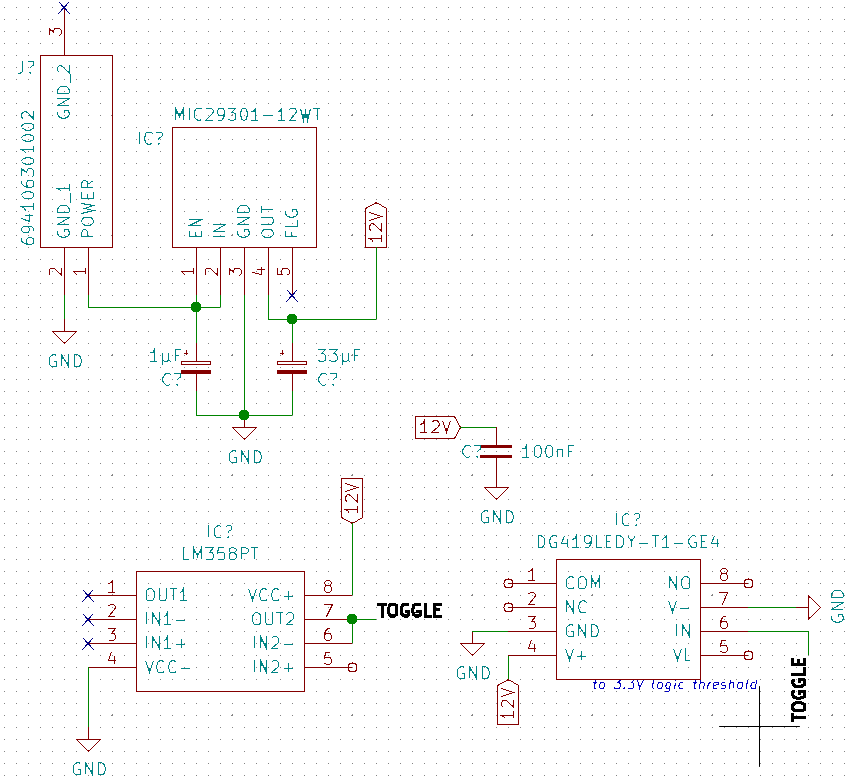
Analogue Switch (SPDT) -
DG419LEDY-T1-GE4
Datasheet: Vishay - DG41XLE Analogue Switches
Op-amp - LM358PT Datasheet: LMX58 Op-amps
Using a microcontroller's GPIO, and a non-inverting buffered op-amp output (LM358), I will be controlling the analogue switch mentioned above. Vcc of both the op-amp and the analogue switch is 12V.
I tested this on a breadboard with 3 switches and only the micro's GPIO at first, but saw that the output high voltage of 3.28V had dropped to about 3.05V. So I added the buffered op-amp stage and that resolved it. I don't have enough switches to do more testing, but I plan to be using about 27 in total, maybe a few more.
- Should I add more op-amp stages for better load distribution? Maybe 3 op-amps handling 9 switches each?
- Page 3 of the switch's datasheet says the max. input current draw is 1µA. So a total draw of about 30µA.
- Page 7 of the op-amp's datasheet says the typical output source current is about 40mA, albeit that's for a Vcc of 15V and a lower output voltage. But 10s of µA for the switches vs. 10s of mA for the op-amp really shouldn't be an issue for the op-amp is my thinking.
- ...but 3 switches had a non-negligible effect on the GPIO output, which is rated to source upto 15mA at most. So why did this happen?
- The micro will be driving the output at its slowest setting, and there will be no high rate of back and forth switching going (maybe switched back and forth once or twice an hour)
Would a single 100nF decoupling capacitor suffice for each op-amp's supply rail in practice?
With a peak current draw of 30µA, a 0.6V/µs slew rate for the op-amp (5.5µs rise time to 3.3V), and assuming a bad power-supply ripple of 100mV:
Then the required capacitance is (30µA x 5.5µs)/0.1V = 1.65nFThe switches will all trigger at once.
Schematic below, note a number of pins are still not connected as it's in progress, and only a single switch is shown.


