8
\$\begingroup\$

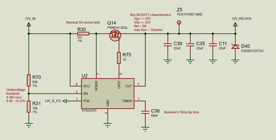
I'm trying to create a circuit that will cut out if >5A is drawn downstream, using the TPS24701 hot-swap controller. It looks designed for exactly this sort of thing. Here's my cicrcuit:

circuit diagram

I clearly need some sort of protection around the MOSFET because, when 12V_RELAYS is connected to an electronic load, and the current draw is increased to above 5A, instead of the MOSFET turning off, the FET emits some magic smoke, and fails into a mode where it will transmit current, but at high resistance, getting very hot.

It seems to me that the FET is trying to be turned off at the right time, but the process of turning it off when the circuit it fully loaded is causing the FET to fail. My question is: Why? And how do I fix it?

Conjecture: My current working theory is that during turn off, the gate voltage is being brought low slowly (by the 10mA current sink described in the datasheet), which puts it in some sort of linear mode for a bit, but this overheats the FET. I tried replacing R75 with a 0R resistor and the same thing happened, so I don't know how to reduce the turn-off time further. Do I just need to choose a different FET? If so, what are the critical parameters here?

Any help is greatly appreciated!

\$\endgroup\$
2
  • \$\begingroup\$ 'the FET emits some magic smoke, and fails into a mode where it will transmit current, but at high resistance, getting very hot' this made my day :) \$\endgroup\$
    – 2e0byo
    Commented Oct 8, 2021 at 11:25
  • \$\begingroup\$ Instead of theoretizing, what about a little experimentation? Put a beefy diode parallel to the MOSFET (so that it shunts the excess current around once the MOSFET closes and thus limits it Vds so that it doesn't insta-fry), connect a transient recorder/scope/multimeter and try overloading it. Then see how Vgs and Vds responds. You could also temporarily replace R30 with a higher resistance to use safer currents for experimentation. \$\endgroup\$
    – TooTea
    Commented Oct 8, 2021 at 13:17

3 Answers 3

10
\$\begingroup\$

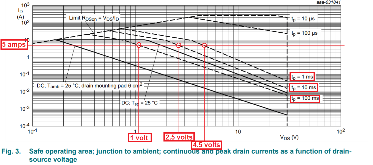
When your circuit enters current limiting, the MOSFET is under-driven on its gate to ensure that drain current doesn't exceed 5 amps. This feature means that you have to examine the safe operating area of the PXN010-30QL MOSFET in case it might fry: -

enter image description here

Do you see the problem?

Basically, the voltage across drain and source of the MOSFET has to rise in order to prevent more than 5 amps entering the load. Given that your input supply is 12 volts, quite possibly up to maybe 10 volts is across drain and source.

To operate continuously (solid black graph in picture) AND, with 10 volts across drain to source, requires that the drain current be below 4 mA (according to the SOA graph above).

Your device will "pop" after a few milliseconds I estimate.

My current working theory is that during turn off, the gate voltage is being brought low slowly, which puts it in some sort of linear mode for a bit

Correct. Then it's going into thermal runaway due to being held in linear mode too long with too high a drain current. It's not designed for linear operation; it's designed for what it says on page 1 of the data sheet: -

Superfast switching with soft-recovery
DC to DC conversion
Battery management
Low-side load switch
Switching circuits
\$\endgroup\$
9
  • \$\begingroup\$ Easy fix would be to reduce the trip time to less than 100 µs, which according to the graph should be in safe area. I.e. change C36 to 680 pF. But charging the 66µF capacitors to 12V at 5A would take 144 µs, which could cause it to trip on power-on inrush current. \$\endgroup\$
    – jpa
    Commented Oct 8, 2021 at 8:02
  • \$\begingroup\$ I recommend choosing a MOSFET that is fit for purpose rather than try and change the purpose (which I believe to be a continuous current limiter). \$\endgroup\$
    – Andy aka
    Commented Oct 8, 2021 at 8:05
  • 2
    \$\begingroup\$ TPS24701 does not do continuous current limiting, it cuts off completely after the delay time set by capacitor on TIMER pin. \$\endgroup\$
    – jpa
    Commented Oct 8, 2021 at 8:13
  • 2
    \$\begingroup\$ I agree - it should be possible to find a MOSFET that can tolerate e.g. 1 ms of the 5A@12V pulse, giving much more leeway in selecting the trip time. \$\endgroup\$
    – jpa
    Commented Oct 8, 2021 at 8:56
  • 1
    \$\begingroup\$ Yeah, I think that restarting is what is killing the MOSFET - keeping it in linear region for the 9 ms trip time every time, while the maximum safe time is about 0.1 ms. If it does not die the first time, it certainly will pretty soon. \$\endgroup\$
    – jpa
    Commented Oct 8, 2021 at 13:41
2
\$\begingroup\$
  • Put a 16 V Zener connected to your NMOS VGS to clamp and protect the gate.
  • Your trip time is way too long for a short circuit condition: after 500 µs under a short circuit event all transistors will break.
  • Are you in constant current mode on your load? Go to constant resistance as if the voltage saw by the load drop (like when the IC is sinking the charges in the gate), it will decrease its internal resistance to keep the current constant. In its linear region, your NMOS will break as its resistance is high.
  • You say the IC sinks 10 mA but you didn't calculate the voltage drop time of the RC (gate resistor - gate capacitor) network. Check the time to empty the gate and get the VGS below its threshold.
  • Your chip is doing active current limiting -> your NMOS is driven inside its linear region. Check the SOA.
\$\endgroup\$
0
\$\begingroup\$

If you still want to use the TPS24701 and the PXN010-30QL MOSFET, here is what I have found so far following the TPS24701 step by step design example:

Step 2:The maximum DS ON resistance has to be less than 28 mΩ (140mV/5A), which the MOSFET has when the gate voltage is above 3 Volts at 5A (fig 8 in its datasheet), but it grows very rapidly for lower gate voltages. The CSD16403Q5A MOSFET example shown in the TPS24701 is about 10 times less, which may explain why the TPS24701 works for CSD16403Q5A but not for PXN010-30QL.

Step3: Using @AndyAka Oct 14:43 chart and @jpa Oct 8 8:02 comment, the tFLT value of 500µs since to be more appropriate for a gate voltage of 10 Volts and DS current of 5 A. In this case CT=C36 needs to be:
500µs * 10 µA / 1.35 V = 3704 pF, and:
tON = tFLT - (MOSFET CISS) * VCC / 2) / Igate so:

tON = -500µs - 580pF * 6V / 20 µA = 0.326 ms which brings
COUT = (C39+C35+C11) = tON * 5A / 12 V = 136 µF.

One thing that has not been explained in your question is if you need a Hot-Swap Controller with a Timed Overcurrent Breaker, which is what TPS24701 is, or just an overcurrent protection circuit, like an electronic circuit breaker, that will shutdown when the current exceeds 5 A even considering an inrush current.

If that is what you are looking for (a current limiting circuit that will shutdown at a specific current) you may want to consider the following video https://m.youtube.com/watch?v=fqeUpATJlZY which presents the basics of a current limit circuit that can be applied to any circuit. The part2 and part3, although having a different name (look in the video description for their links), builds on it with the final solution presented in part 3.

\$\endgroup\$

Your Answer

By clicking “Post Your Answer”, you agree to our terms of service and acknowledge you have read our privacy policy.

Not the answer you're looking for? Browse other questions tagged or ask your own question.