1
\$\begingroup\$

I have a project which needs a analog video signal & some control data sent on a coaxial cable, I came up with some ideas and I asked about it and some interesting answers were received (Multi "Master "Coaxial Driver Design).

Since then, I created another design(not tested yet!) and I want to ask if anybody can give me a second guess about it.

enter image description here

Since @Andy aka recommended me to use a HF signal carrier for my control signal I found this SI4432 which is a ISM transceiver, works from 230MHz to 930MHZ (the majority of the dev boards are for 433MHz). Since this is a RF transmitter it shouldn't be any problem because I never attached the antenna and just use the coax to reach my final "point" (if I make a mistake please correct me).

Now, my "imaginary" problem is from my knowledge and some research I found that I will need a diplexer to separate the HF & LF signal (analog video is around 8MHz - control data 433MHz carrier).

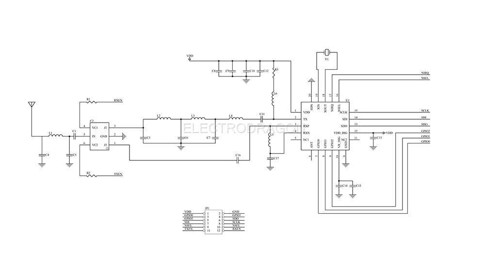
Since the SI4432 has already all the matching impedance stuff and I believe a duplexer (since this is a transceiver), I don't know if my Diplexer will interfere with the Duplexer of the SI4432 board.

Some tips & tricks would be really appreciated. Thx

This is the schematic for the SI4432 board that I want to buy. (Sorry for the quality, I tried to search one much better, but no luck :( )

Coaxial Transceiver

\$\endgroup\$

1 Answer 1

1
\$\begingroup\$

The diplexer is essentially a frequency-selective signal combiner, with a low-pass filter in the input path from the video source, and a high-pass filter in the input path from the SI4432. The combined signal is then transmitted over the coax and split up again in high- and low-frequency parts at the other end by the same diplexer used as a signal splitter. This is frequency-division multiplexing.

The duplexer on the SI4432 board is implemented as a transmit/receive (T/R) switch, which means that the chip can either send or receive, but not both at the same time (half-duplex). This technique of switching between transmitting and receiving time windows is called time-division duplexing.

Because one works in the frequency domain and the other in the time domain, I cannot imagine that they will interfere with each other. It's just the "direction of transmission" of the high-frequency control signal that changes.

\$\endgroup\$
3
  • \$\begingroup\$ Thanks for the explanations. So the final low-pass filter on the SI4432 board will not have a problem to be combined with a high pass filter from my diplexer ? I ran some simulations with LTSpice and for the 433MHz bandwidth was a -3db response, although since this IC was meant for RF transmission I believe that the receiver can handle that. \$\endgroup\$ Commented Oct 9, 2021 at 9:25
  • 1
    \$\begingroup\$ No, I don't think so. The SI4432 board low-pass filter is designed to filter out higher frequency harmonics from the transmit signal of the chip, but let the desired 433MHz signal pass through. Your diplexer filter (on the SI4432 path) is designed to filter out the lower frequency video signal, but also let the 433MHz signal pass. Both of these filters in series add up to a band-pass filter with 433MHz in the passband. You may experience a small attenuation, as in your simulation, but yes, this is nothing in comparison to the typical path losses the transceiver is designed for. \$\endgroup\$ Commented Oct 10, 2021 at 9:54
  • \$\begingroup\$ Thank you a lot for explanations. Nice to know that somebody agree with you. \$\endgroup\$ Commented Oct 10, 2021 at 18:25

Your Answer

By clicking “Post Your Answer”, you agree to our terms of service and acknowledge you have read our privacy policy.

Not the answer you're looking for? Browse other questions tagged or ask your own question.