0
\$\begingroup\$

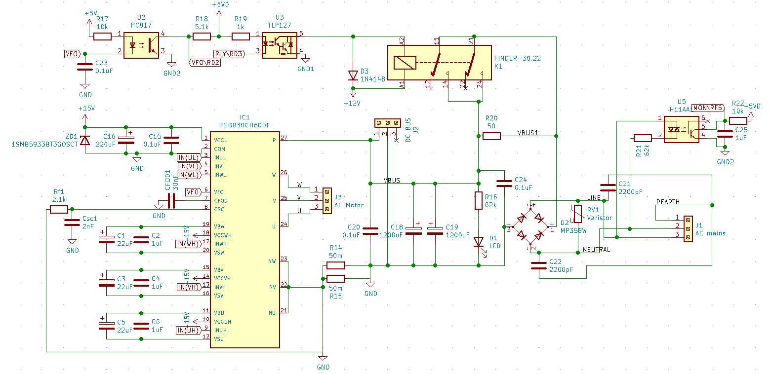
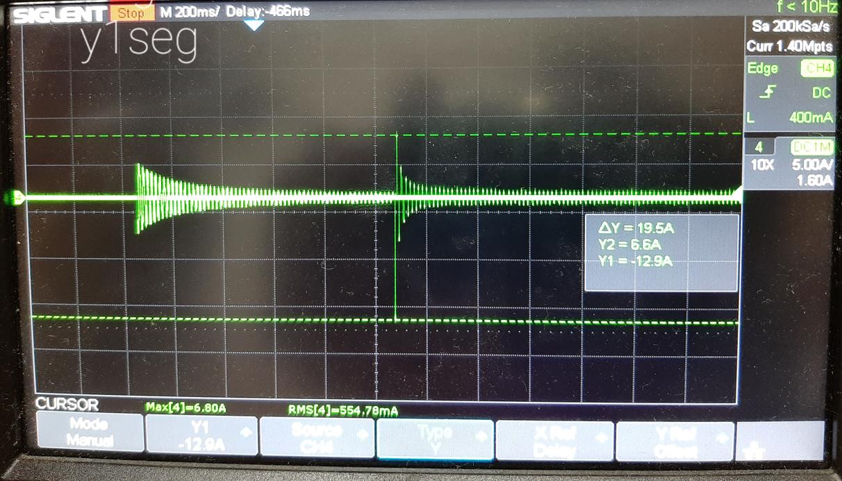
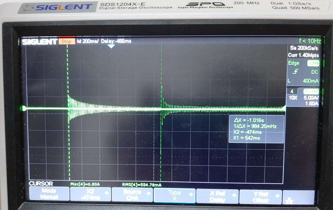
I have been working in a VFD using an AC motor driver FSBB30CH60DF and making control of it using a dspic30f4011. As you can see in the attached circuit schematic, the mains supply is a single phase 120VAC and when the circuit is powered up, the relay bypasses the resistance after 1 second (the current waveform in green was measured with a clamp meter in the LINE node). I can power it up a few times and everything works well, until the last time I power it up: the driver burns out and does a short circuit on its terminals "P" and "N" which is connected to the VBUS. At the beginning I thought it was because I had not enough spacing between the traces but it was not this reason. What could I implement to the circuit to protect the AC motor driver (I was thinking of using a solid state relay or a thermistor in order to lower the inrush current but I am not really sure if this is going to work)?

Thank you in advance.

enter image description here enter image description here enter image description here

EDIT: This is the documentation about the driver:

https://www.onsemi.com/pdf/datasheet/fsbb30ch60df-d.pdf https://www.onsemi.jp/pub/collateral/an-9760jp.pdf

\$\endgroup\$
2
  • 1
    \$\begingroup\$ The inrush limiter is to protect the bridge rectifier - not IC1 - as far as I know. \$\endgroup\$
    – Transistor
    Commented Oct 25, 2021 at 23:47
  • \$\begingroup\$ Please add the FSSB30CH60DF datasheet link into your question. \$\endgroup\$
    – Transistor
    Commented Oct 26, 2021 at 1:12

1 Answer 1

0
\$\begingroup\$

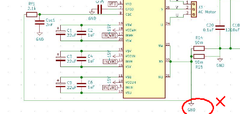
This appears to be an oversight to short out the Current Sense CSC signal which is used to protect the driver by current limiting. The uC must also use low acceleration to limit the torque and current surge for speed changes and not exceed the thermal design limits.

enter image description here

\$\endgroup\$
3
  • \$\begingroup\$ Thank you for your response Tony, I have followed the suggestions mentioned in the ON-semiconductor AN-9760 of the manufacturer which recommends to do that connection between one side of the shunt resistor and VBUS ground. \$\endgroup\$ Commented Oct 26, 2021 at 0:53
  • \$\begingroup\$ OK then report all the measurements for current and temp rise with thermal resistance of your design while fixing your schematic. When testing a new design its always a good idea to have a list of critical specs and a test plan to safe test it with non-destructive testing to verify all your assumptions for inputs and outputs. \$\endgroup\$
    – D.A.S.
    Commented Oct 26, 2021 at 1:09
  • \$\begingroup\$ Tony, that was the reason of the short circuit, now I can continue with the measures you suggested. Thank you. \$\endgroup\$ Commented Oct 27, 2021 at 19:13

Your Answer

By clicking “Post Your Answer”, you agree to our terms of service and acknowledge you have read our privacy policy.

Not the answer you're looking for? Browse other questions tagged or ask your own question.