3
\$\begingroup\$

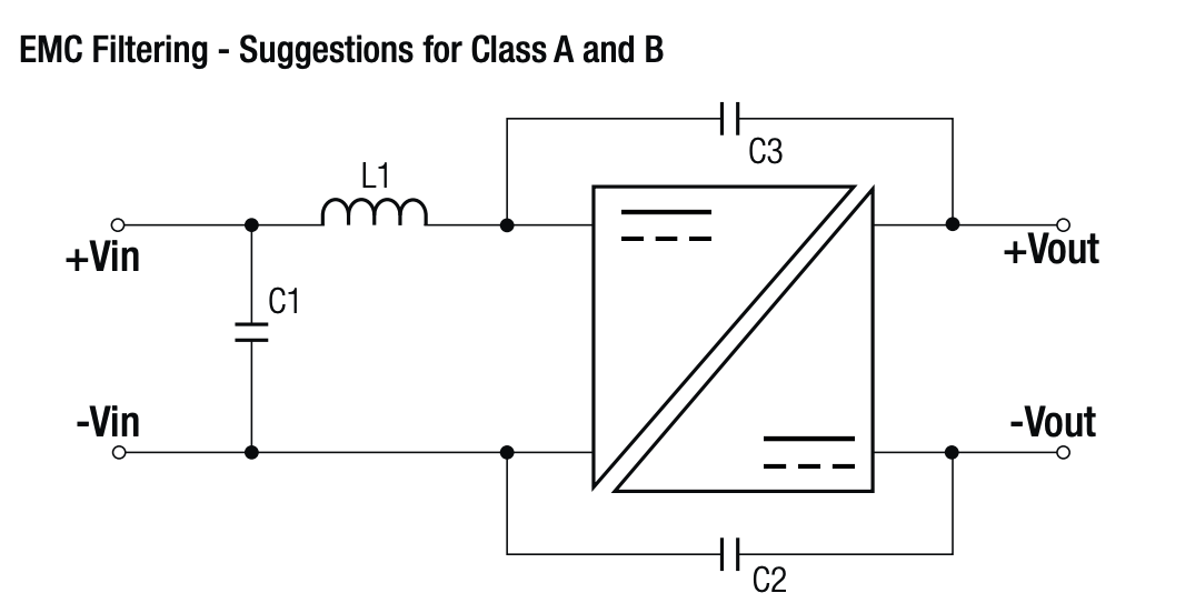
I found this EMC Filtering circuit in the datasheet of the RFB-0505S DC-DC Isolated voltage regulator.

What is the purpose of C2 (1nF) and C3 (2.2nF)?

enter image description here

I don't understand why they are suggested. Is C3 not going to create a short circuit between the input supply and the output supply? What is C2 doing? Making a connection between the two grounds?

\$\endgroup\$
2
  • 2
    \$\begingroup\$ Long story, Google for : SMPS Y Capacitor. \$\endgroup\$ Commented Oct 30, 2021 at 23:13
  • \$\begingroup\$ Full isolation is hardly feasible nor desirable. What isolated PSUs try to achieve is low frequency isolation. On the other hand, a say "golden" rule of EMC is to keep as much or the appliance RF-grounded as possible.. Capacitors achieve both, RF-grounding and LF isolation. \$\endgroup\$
    – tobalt
    Commented Oct 31, 2021 at 7:36

1 Answer 1

5
\$\begingroup\$

The purpose is common mode suppression.

Without the caps, the isolated output will be floating and have very high impedance to the input side, but that is a problem because any stray capacitance in the transformer would couple the high frequency square wave switching waveform to the output, but the caps cause the output to have lower impedance and the small stray coupling can't cause much fluctuation of the output voltage.

C3 will be a short circuit at high frequencies but not at DC. Yes C2 does the same and makes the grounds connected at high frequency AC.

\$\endgroup\$

Your Answer

By clicking “Post Your Answer”, you agree to our terms of service and acknowledge you have read our privacy policy.

Not the answer you're looking for? Browse other questions tagged or ask your own question.