1
\$\begingroup\$

I want to use a micro-controller (like an Arduino) to:

  • Charge an external capacitor
  • Measure voltage across the capacitor
  • Capacitor discharge rate as low as possible.
  • Capacitor discharge rate while using ADC to measure voltage as low as possible.

The microcontroller has

  • DAC (to charge capacitor)
  • ADC (to measure capacitance)
  • Multiplexer to attach DAC/ADC to whatever pin you want
  • I use a multimeter to measure resitance between pin 0 and pin 1 = 1Mohm (Q1 is pin0-1 resistance called chip resitance? What is the name?)

I can attach a capacitor between pins 0 and 1 however it will discharge as 1Mohm resitance isn't very high.
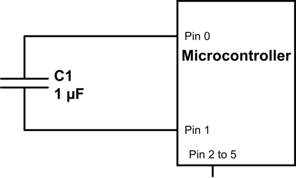
schematic

simulate this circuit – Schematic created using CircuitLab

Question:

  1. Is the pin 0 to 1 resistance called chip resistance? What is the name?
  2. How can I reduce the capacitor discharge after I charge it with the DAC?
  3. How can I reduce the discharge while measuring voltage with ADC?

My actual chip is the NHS3152. I am looking for any solution, even one with other components to be added.

EDIT EXTRA CONTEXT INFORMATION

I was thinking of using the capacitor as an X-ray detector:

  1. X-rays would interact with the dielectric to create e-h pairs
  2. The electric field present on the charged capacitor would separate the charges
  3. This would affect voltage across capacitance.
  4. Measure the voltage with NHS3152 and have a working device.

If the capacitor discharges over time, then the field within the dielectric would change, separating the e-h pairs less, so low-discharge is important.

\$\endgroup\$
25
  • 7
    \$\begingroup\$ what's the purpose? \$\endgroup\$ Commented Nov 3, 2021 at 12:07
  • 1
    \$\begingroup\$ I use a multimeter to measure Resitance between Pin0 & Pin1 = 1Mohm ( Q1 is Pin0-1 resistance caleld chip resitance? what is the name? That is a meaningless measurement. Depending on how you measure and/or configure the chip, you will get completely different values. Why? Because those pins are IO pins and that means they can be configured as input/output/ with or without pullup (and/or down) resistor or they can be tri-state and have a high impedance. This all when the chip is in operation (powered on). \$\endgroup\$ Commented Nov 3, 2021 at 12:15
  • 3
    \$\begingroup\$ All-in-all: there's a complex circuit connected to those pins, measuring the resistance with a multimeter is pointless. You are just fooling yourself if you think that that gives you reliable information. I also agree with @user253751: explain WHY you do this, what are you trying to achieve? \$\endgroup\$ Commented Nov 3, 2021 at 12:15
  • 1
    \$\begingroup\$ "as 1Mohm resitance isn't very high" Eh? 1 Megaohm is very high, especially for the purpose of charging/discharging caps. Are you sure you don't mean milliohm, m prefix, like they taught us back in school way before enrolling in actual engineering studies? \$\endgroup\$
    – Lundin
    Commented Nov 3, 2021 at 12:22
  • 2
    \$\begingroup\$ You will need to study datasheets and look at if any leakage is specified. If it is not you might want to make a test setup and just measure it. You will need to do something like that anyway, see what happens with/without the X-ray to prove that your scheme actually works (or not). \$\endgroup\$ Commented Nov 4, 2021 at 10:33

0

Your Answer

By clicking “Post Your Answer”, you agree to our terms of service and acknowledge you have read our privacy policy.