0
\$\begingroup\$

I took this circuit from the book Diode,Transistor & FET Circuits Manual by R.M. MARSTON. It is for wide range voltage regulation.

I tested this circuit and it works very well.

The main problem is that at first I used a C3150 NPN transistor and 100mA load. The transistor serves 100mA load but as soon as I attach a 300mA load the voltage drops and the transistor started to heat up.

Then I tried a TIP122 Darlington transistor, hoping it would help to provide more current but the Darlington pair does the same as previous and wasn't able to provide the 300mA current.

On the other hand the 7812 voltage regulator ICs are able to provide sufficient current.

Will a transistor like the D1047 help to provide more current or is something wrong with the circuit itself which prevents it from providing more current?

Isn't the transistor supposed to serves the current here? Can I get more current with the same transistor with any other configuration?

There is one more property which I observed that if I place the load across R1, it was able to light up the bulb with 300mA current. Why is a normal Zener able to provide the current but not the C1350 transistor? What am I missing here?

Note: I am using a 5V Zener instead of the 12V and 12V input to this circuit. All other component values are the same.

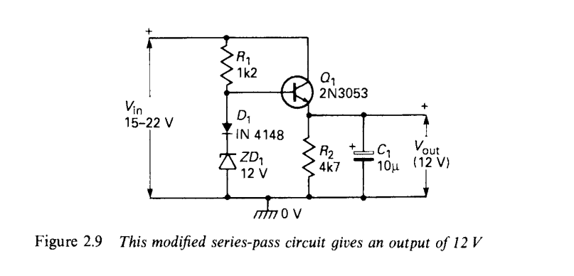
enter image description here

\$\endgroup\$
5
  • \$\begingroup\$ "C3150 NPN Transistor" contradicts "C1350 Transistor" - so, get your part numbers right and, provide data sheet links to the transistors, bulb and zener diodes used. \$\endgroup\$
    – Andy aka
    Commented Nov 4, 2021 at 10:28
  • \$\begingroup\$ I would check the hFE and make sure there's enough base current. Although you say it also doesn't work in a Darlington configuration which rules out that problem... I would check it anyway \$\endgroup\$ Commented Nov 4, 2021 at 10:45
  • \$\begingroup\$ Very roughly , the current in the zener is 10/1k2=8mA max if Vin = 22 V. So for regulation, the ib current can not be greater than 8mA. With a "beta" of 20 (example) ... ie can not be greater then 8*20mA = 160 mA ... \$\endgroup\$
    – Antonio51
    Commented Nov 4, 2021 at 10:46
  • \$\begingroup\$ Why bother when you can use a cheap DC-DC converter and an inductor with overall > 80% efficiency ? \$\endgroup\$
    – citizen
    Commented Nov 4, 2021 at 11:23
  • \$\begingroup\$ The C1350 is not much suitable for this purpose because of low Hfe (10-40) so with Hfe=20 you would have to increase the zener current to 15mA (R1 about 400ohm). The darlington is ok but due to 2xBE junction in series you must change the zener diode to 5v6 or use 2xD1 in series. \$\endgroup\$
    – user208862
    Commented Nov 5, 2021 at 3:06

2 Answers 2

1
\$\begingroup\$

Linear voltage regulators are pretty inefficient. At 300mA, and dropping 12V to 5V, you are dissipating 0.3 x (12 - 5) = 2.1W in the transistor.

You need to provide an adequate heatsink to the transitor, or it will burn out. The same applies if you use a 7805.

\$\endgroup\$
1
\$\begingroup\$

The transistor serves 100mA load but as soon as I attach a 300mA load the voltage drops and the transistor started to heat up.

It's a linear voltage regulator and the efficiency will be always small: around 25% for practical applications 12 Vin -> 5 Vout.

For each electrical Watt delivered to the load you waste 3 Watt in heat.

You can add/remove parts, optimize the bias point, but the efficiency will always be small.

To increase the efficiency the input voltage must be the closest possible to the output voltage, for example: 15 Vin -> 12 Vout

It's this type of power conversion system that is inherently low efficient.


Take a look here:

https://eepower.com/tools/linear-regulator-calculator/

\$\endgroup\$

Your Answer

By clicking “Post Your Answer”, you agree to our terms of service and acknowledge you have read our privacy policy.

Not the answer you're looking for? Browse other questions tagged or ask your own question.