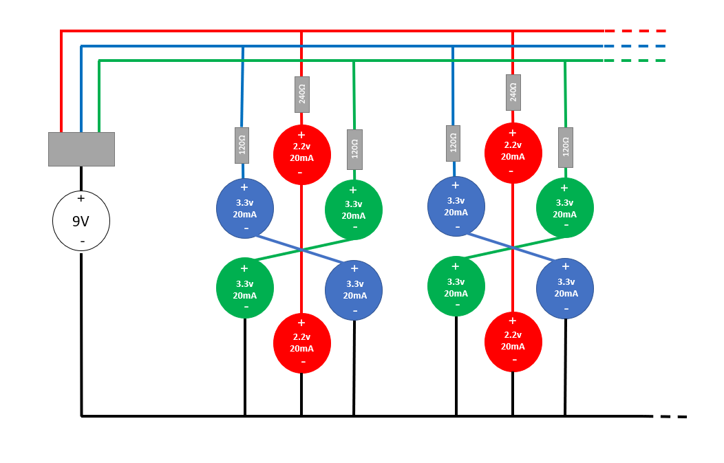
One other thing is that the panel would be powered by an external timer (not from an Arduino) so a transformer of some sort would be involved
This is not going to work because you'll be using an AC-DC switching power supply or driver for your LEDs, and these have enough storage capacitance to stay on for a significant time when mains power is cut off. So if you use a standard darkroom timer with that, the switching power supply will add some unspecified and potentially variable delay both at turn-on and turn-off, and that would suck.
On top of that, I assume for multicontrast paper you will want to control the power of green and blue LEDs separately.
So if you use one timer, that means both colors will be on for the same amount of time, so then you need two dimmers, for example PWM, with one dimmer per color. So you set the time on the timer, chose a contrast setting, which decides the PWM ratio of both colors. In this case, if you use the timer to control the main power supply, then when it turns on and off its voltage will ramp up and down. The red LEDs and the green LEDs will turn on at different voltages, so the reds will shine for longer... the dimmers may also do funky stuff at power-up, screwing up your contrast settings... and the turn-off time of the power supply depends on the discharge time of the high voltage capacitors, which depend on the current drawn by the LEDs, which depends on the contrast settings. So it will be a mess.
If you have RGB LEDs, you can have a nice feature: by enabling only the red ones, you can even check focus and framing with the paper in the easel. Could be useful if you want to do multiple exposures... Then you need the power supply to be always on (not controlled by the timer) so the red LEDs will light when you flip a switch or turn a dimmer knob.
So, if you have a darkroom timer that you like then the simplest option would be to use it to drive a relay, or an AC optocoupler, that either controls a MOSFET to turn on the LEDs, or simply sends a signal to the PWM dimmers so that they turn on. That way the timing of the light would be exactly what you set on the darkroom timer, and the power supply is always on. That also saves a power supply for the arduino if you have one, or for extra circuits.
Next question is the optics: you need uniform lighting on the film.
Usually in an oldskool condenser enlarger that would be an incandescent point source with a big condenser lens in front that produces parallel light rays.
To emulate that with LEDs you would need a powerful yet small LED, so it would have to be a COB, but that is only available in standard RGB wavelengths, and you need nonstandard wavelengths.
So you'll probably end up with lots of LED chips soldered on a 4x5 PCB instead. This will not produce parallel light rays, so it will be more like a diffusion enlarger instead of a condenser enlarger, and it will produce different looking prints. I've never used a diffuser enlarger, so I'm not the one to ask about the difference between diffuser and condenser, but I heard , purists really care about it, and if you're using large format I'll assume you care about every little detail that affects quality, so I should mention it.
Anyway, because individual LEDs will produce different light outputs, at the same current, there is a risk of hotspots or non-uniform lighting on your film. So you should try to get binned LEDs, then make a really good diffuser. Perhaps a mirror box with diffuser sheets on top and bottom. You can take a picture with a digital camera at low exposure to judge uniformity of lighting. If you use resistors, you could add several footprints for resistors in parallel, so if you notice some of the LEDs are a bit weak, you can easily adjust their resistor values.
If you need lots of power I would recommend a metal core PCB with a heatsink on the back, you can get them at nice prices from jlcpcb for example. I'm not sure it is a good idea to use a fan for cooling, if it vibrates that could reduce sharpness. In any case thermal design is important because light output of LEDs depends on temperature so if they heat too much, both your timings and contrast settings will be off.
Another issue is led Vf (forward voltage). Unless the LEDs are accurately binned, it doesn't match very well between LEDs, and it also depends on temperature. So if you use resistors to set the current, it will increase with temperature. LED efficiency decreases with higher temperature. Don't count on these two compensating each other. So if you do a series of prints, the first one will be different from the last as the LED panel heats up. Since red and green have the same Vf temperature coefficient but different resistors, they will drift differently, so the first print and the last will also have different contrast. Temperature also changes the wavelengths.
Also if you use a low thermal mass PCB, or if the thermal transfer between the LEDs and PCB is not very good, then it will heat quickly, so a one second exposure may output a bit more light than a half second exposure. What a mess lol.
So yeah, might be a good idea to use a metal core PCB, screwed on top of a big heat sink. Even if power is quite low, thermal mass and constant temperature means less headache, and it's not much more effort compared to soldering all those LEDs. A big chunk of aluminium will also spread the heat and prevent the center from heating more than the sides.
Make sure you have enough LEDs and enough power to have usable exposure times... it's better to make a PCB with too many footprints and not solder the LEDs, than the other way around.
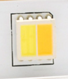
Green and blue LEDs should be as close as possible and side by side to try to make them into a dual-color point source, like that:

Since the paper doesn't care about red, placement of reds is not critical.
Now if you want current to be constant and not depend on LED Vf, matching, temperature, etc, then it would be better to use current sources.

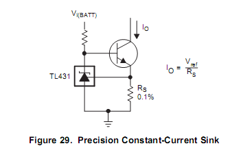
This one is nice, cheap, and temperature compensated. The bipolar transistor can also be substituted with a MOSFET, in any case it should be chosen to handle the current and dissipation. You can apply PWM to the top of the resistor (labeled "Vbatt") and control the output. TL431 sets voltage on Rs to 2.5V, so current is simply 2.5V/Rs. No need for 0.1%, a cheap 1% resistor is fine.
With a 24V power supply instead of 9V, you can wire a lot more LEDs in series, and use less current sources. You can also use a recycled 19V laptop brick.
If you use 24V, then you can wire the blue LEDs in series in strings of 6, which will give a maximum voltage of about 20V, leaving 2.5V on the current setting resistor Rs above and 1.5V Vce for the transistor. If you use 20mA current, that means Rs=120 ohm ; it will dissipate 50mW so a 1/4W resistor is fine, and the transistor can be a jellybean 2N3904, BC546/7 or whatever.
If you also group the reds in strings of 6 that will only make 10.8V so you can wire more in series to prevent the transistor from having too much Vce, which would then need to be a higher power one with a heatsink.


