0
\$\begingroup\$

Looking for suggestions as to designing the ground layer of a PCB.

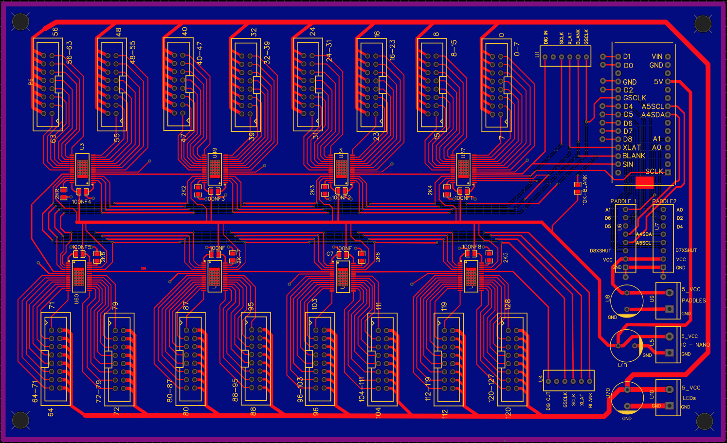
Effectively the board is a LED driver. It has a number of TLC5940 shift register ICs and their signal paths coming from an Arduino, the ICs control a large array of LEDs. There is a sensor input or two on the Arduino. Specifically, I’m trying to make sure that all of the grounds have a clean return path through the bottom copper layer. I’ve routed any and all GNDs (power, ICs, Arduino, Sensors) through vias to this bottom copper ground layer. As I understand it though, that is only half the battle.

Power is getting to the Arduino and it is functioning. The sensors, though a long way away from board, are getting the required power and working. Ive tested the power bus traces out to the individual LEDs and they have enough voltage to do what they need to do when the power gets pulled down by the IC. I've had this circuit working with sixteen TLC5940/512 LEDs on a breadboard but now I'm getting nothing with these ICs on the PCB. Not even a flicker. The ICs just don't seem to be taking any power

My problems could be the board design itself, power management, or they could be my inability to solder those tiny little SMD components. Either way, I want to get the power/ground design checked/fixed before I send away for yet another set of boards, this time with Pick and Place.

BTW, I realize that this is a very inelegant solution for a LED driver, but it is the solution that I need nonetheless. It’s for an art installation that is already built, coded, so I have to make the circuits work as such.

Power - three 5V lines from a single 5V 40A Meanwell DC power supply. 5V line for the Sensors, 5V line for the Nano and ICs, and 5V line for the LEDs, separated and decoupled (I think)

IC’s - TLC5940 Shift Registers - TI Datasheet - https://www.ti.com/document-viewer/TLC5940/datasheet/pin_configuration_and_functions#SLVS5159151

Arduino Nano

Sensors - Using three different sensors to bring signals in and out of the Arduino via screw terminals. Per Sensors: The terminals and traces are close to the Nano.

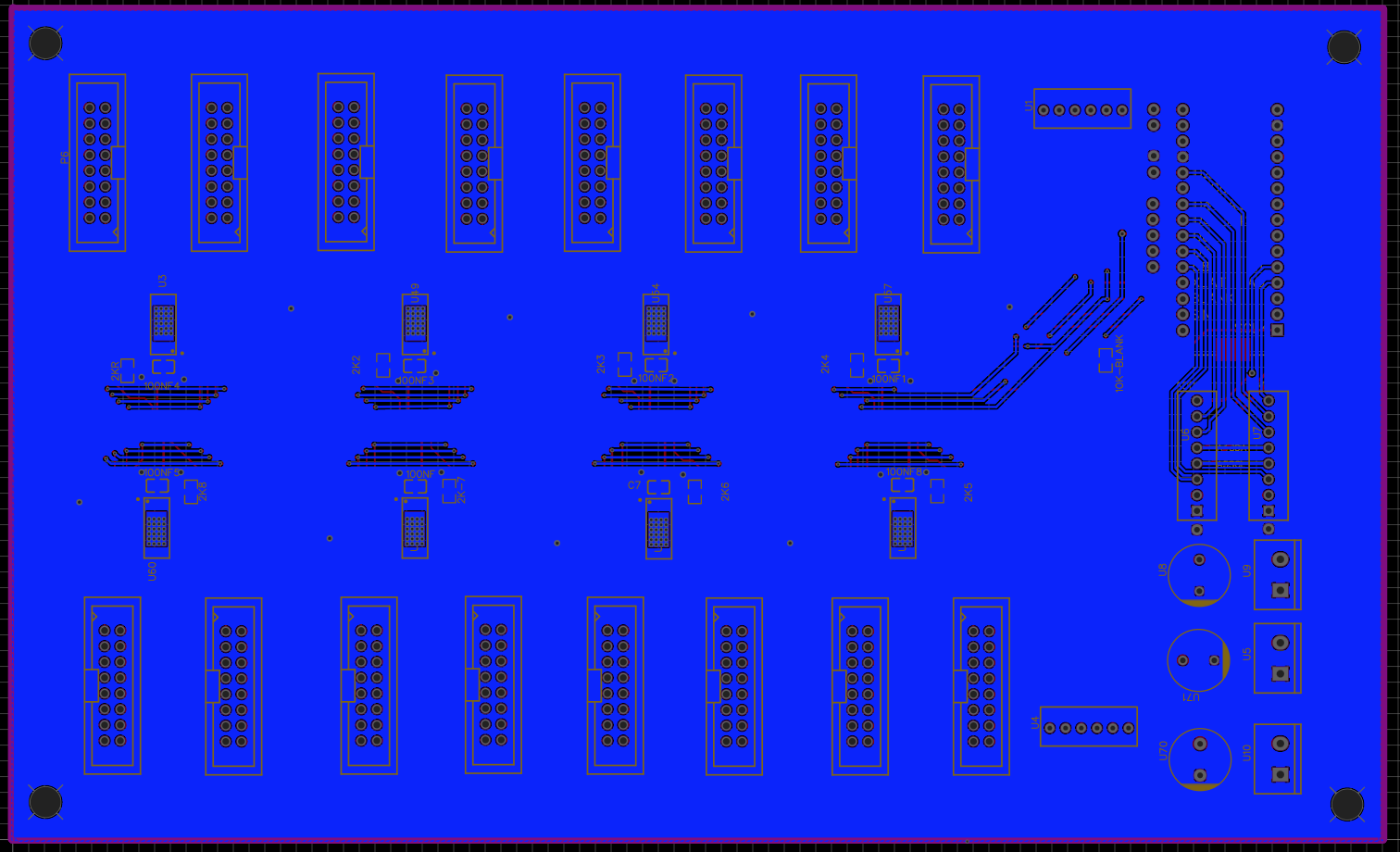
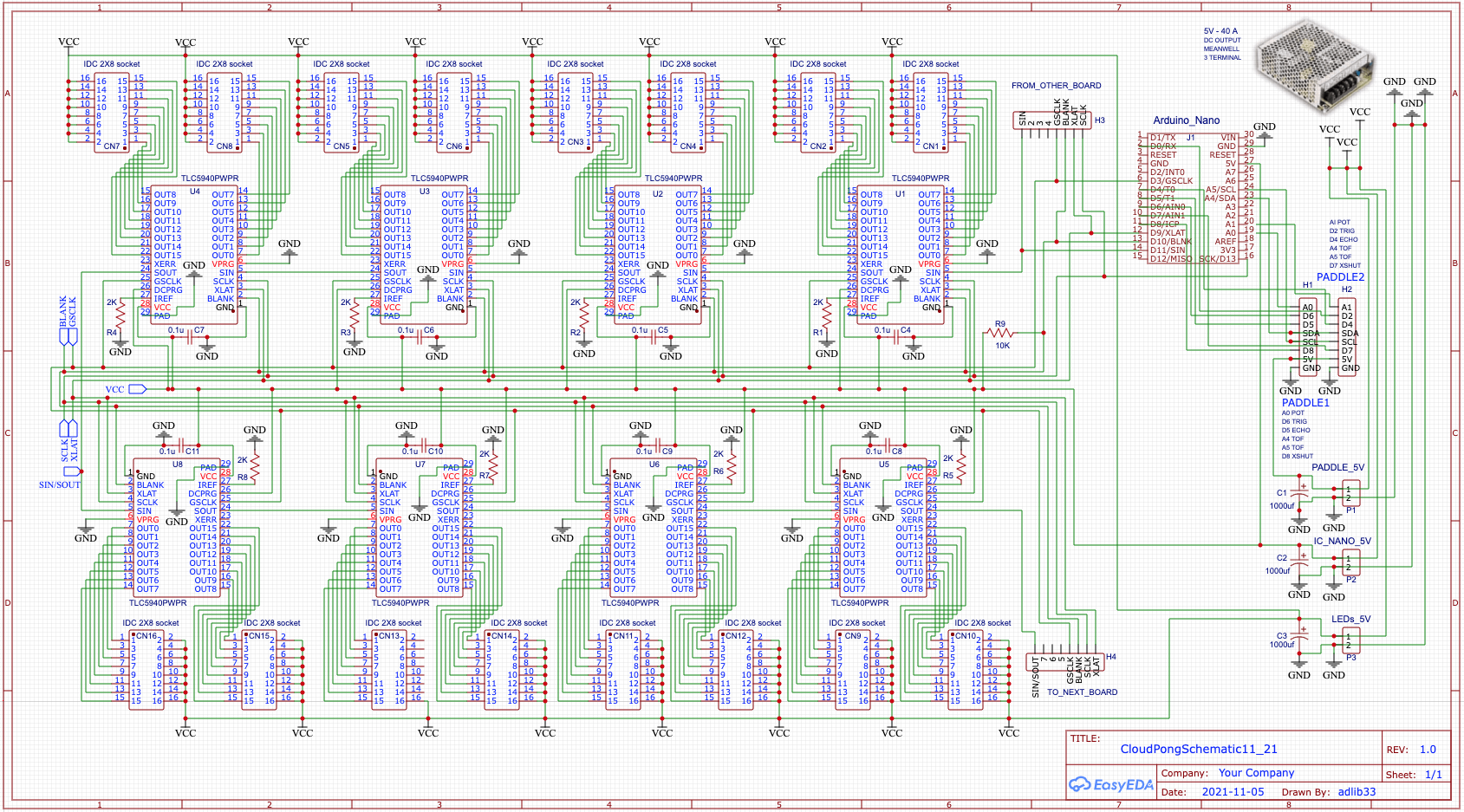
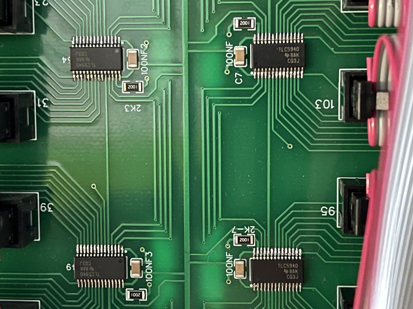
PCB Design Back_Copper_Layer Schematic for TLC5940 Board close-up SMD

[FIXED LINKS] The schematic for this circuit board on EasyEDA. Takes you to their sharing site OSHWLAB -

https://oshwlab.com/adlib33/cloudpongschematic11_21

The PCB - https://oshwlab.com/adlib33/cloudpongpcb

\$\endgroup\$
15
  • 4
    \$\begingroup\$ 40 amps is a lot of current to distribute via traces on a PCB. \$\endgroup\$
    – SteveSh
    Commented Nov 6, 2021 at 20:41
  • \$\begingroup\$ Those tiny connectors are probably rated for a lot less than 40a. How much are you expecting to pull? \$\endgroup\$ Commented Nov 6, 2021 at 21:22
  • \$\begingroup\$ Can you give more details of what does not work? \$\endgroup\$ Commented Nov 6, 2021 at 22:29
  • \$\begingroup\$ The links don't seem to work. \$\endgroup\$ Commented Nov 6, 2021 at 22:32
  • \$\begingroup\$ Can’t answer that correctly. Still very confused about how to figure amperage needs for a circuit. Especially looking at the IC data sheet, I can’t tell exactly how much current it can handle, only can understand the voltage. I know that the ICs are constant current - and it needs to output somewhere between 60 and 120mA. The ICs are clearly 5V to operate but I need the outputs to be able to handle up to sixteen 5V LEDS/forward voltage(although they will not all be on very often) \$\endgroup\$
    – adlib33e
    Commented Nov 6, 2021 at 22:50

1 Answer 1

0
\$\begingroup\$

You have a short (solder bridge) between pins 1 and 2 of the shift register on the bottom right of the photo. Remove it by running a hot iron repeatedly between the two pins, away from the IC. Check the other ICs too!

I think your layout is acceptable. I would thicken the power traces or even flood the top plane with the LED supply. I'm not sure your decoupling, or the three separate supplies for that matter, are very effective or needed. These electrolytic capacitors will have relatively high series resistance and they're far away from the loads. If needed, smaller ceramic caps next to the LED connectors may be better, but I think it should work as it is. The sensors and Arduino already have decoupling on board.

I would run the same supply for the Arduino and the sensors, because if one becomes unplugged the sensors might see voltages on the I2C pins (from the Arduino) that exceed the VCC pin, and that can damage the chips.

A 40A supply is overkill but will not otherwise hurt!

\$\endgroup\$
2
  • \$\begingroup\$ Thank you DamienD. As per your suggestions, I'll re-do the power on the boards so that it is a single line, remove the large caps next to the power terminal, and route 5V lines directly to the components from that terminal. Ordered a Meanwell 5V 20A power supply to suit the projects needs. Just for clarification, should I place a small cap (220?) on the power line, just before the Arduino? (Believe the 5V power-in is raw, has no regulation) As well, the 100nf cap just before the IC's, is it enough decoupling to handle this more direct 5V power? 100nf is what TI suggests in the datasheet. \$\endgroup\$
    – adlib33e
    Commented Nov 7, 2021 at 22:37
  • \$\begingroup\$ @adlib33e if you know the power supply is not very stable or is several meters away from the board then yes, the large electrolytic capacitors could be useful. But they're mostly effective as bulk capacitance (to supply large, slow transients) rather than decoupling (supply small, fast transients). Best to get a decent power supply in the first place (no a priori reason to doubt that Meanwell part though). Values from the TI datasheets should be fine. \$\endgroup\$ Commented Nov 8, 2021 at 12:59

Your Answer

By clicking “Post Your Answer”, you agree to our terms of service and acknowledge you have read our privacy policy.

Not the answer you're looking for? Browse other questions tagged or ask your own question.