0
\$\begingroup\$

I'm modifying an old CRT to take NTSC composite input (it only accepts RF over coax.)

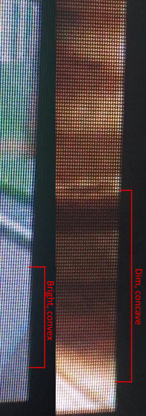
I have got a good signal going in but it has this weird distortion going on.

When the image is dark the pixels may shift left. When the image is bright the pixels may shift right.

How might I go about fixing something like this?

I've tried raising and lowering the capacitance in series with the signal input, no change.

The convex from the bright image is much less noticeable, but the the dim image is very noticeable.

EDIT: UPDATED VIDEO TO SHOW DISTORTION BETTER. Far worse than it may seem from those images. https://i.imgur.com/NOXu49r.mp4

This image shows what I mean:

composite distortion

The RF demodulator outputs a composite signal to pin 13 of the video processing "jungle" chip. I lifted this pin out of the circuit board and then soldered a composite wire to it through a 1uF ceramic capacitor. Before the capacitor I connected a parallel 75 ohm resistor to ground. Look below for some schematics of the TV.

"Jungle" chip datasheet

TV Block Diagram

TV Service Manual (My specific model is the PR1305C1, sometimes written as PR1305C121)

a video showing the distortion effect

\$\endgroup\$
2
  • \$\begingroup\$ I did not read those datasheet, but it sounds like the sync level (on the composite signal) is insufficient. Measure the composite signal on oscilloscope and compare to the standard. \$\endgroup\$
    – jay
    Commented Nov 8, 2021 at 2:53
  • 1
    \$\begingroup\$ Have you verified that the problem is not there when feeding RF in? If it is then it is not due to your modifications. \$\endgroup\$
    – Justme
    Commented Nov 8, 2021 at 5:31

2 Answers 2

3
\$\begingroup\$

This seems fairly normal to me. CRTs don't have perfect geometry. It could be a B+ regulation problem (and since you have it open and have the service manual, you can find B+, I think it's the one the manual calls MAIN VOLTAGE 95V, and make sure that it doesn't droop too much under full brightness) — but more likely it's just that you have a clean signal and you're pixel peeping and noticing something it's always done.

It's probably not a signal path problem, and not related to anything you did while adding composite in.

\$\endgroup\$
1
  • \$\begingroup\$ I just measured the voltage off of that rail from an unpopulated connector 0255. Between 94.1V and 94.3V DC. That shouldn't be enough to cause an issue right? Also, I posted a new video in an edit of the OP to show how bad it actually is, definitely not pixel peeping. Regarding a comment that Justme made, I can't confirm exactly if this was happening with RF but I didn't notice it, and it 100% wasn't as bad as shown in the new video I posted. \$\endgroup\$
    – gonjona
    Commented Nov 10, 2021 at 21:55
3
\$\begingroup\$

This type of distortion is common where the same transformer is used for scanning and creating the high voltage.

It's not the sort of fault that bothered many enough to do anything about it back in the day, It's certainly not a fault with your composite input modification.

\$\endgroup\$

Your Answer

By clicking “Post Your Answer”, you agree to our terms of service and acknowledge you have read our privacy policy.

Not the answer you're looking for? Browse other questions tagged or ask your own question.